Every engine craves cool air: Lots of it. In order to produce as much power as it can, cool air is what every engine needs. From the factory, your Audi’s intake system is designed to work in perfect harmony with the rest of the stock engine operating systems, but we all know there is a lot of untapped performance potential with the 2.0T. Whether this is your starting point, or just another addition to your list of performance upgrades, our Audi B8 A4/A5 2.0T Charge Pipe/Intercooler kits are a perfect modification.
The charge pipe kit fits with your stock intercooler and boasts mandrel bent aluminum charge pipes, smooth flowing silicone couplers, a CNC machined aluminum turbo outlet adapter, and stainless steel T-bolt clamps.
The complete kit with a high flow intercooler yields maximum performance while also adding a sleek yet menacing look through the grille. The increased air flow and reduced turbulence of this system will boost your stock performance, and allow you to get the maximum benefit from any additional performance modifications.
Attractive and easy to install, you can have this system in place in just a few hours or less. Whether you have purchased the charge pipe only kit or the complete kit with our ECS Tuning intercooler, you’ll have everything you need for a trouble free installation. Thank you for looking to ECS Tuning for all your performance and repair needs. We appreciate your business!
Step 1:

Safely raise and support the vehicle
Never get underneath a vehicle that is supported only by a jack. Always make sure that the vehicle is securely supported on jack stands or an automotive lift.
Step 2:
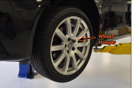

Remove the LF wheel. Here we are using a wheel hanger to support the weight of the wheel when we remove the lug bolts and use of a Protecta Socket will prevent damage to the wheel finish.
Wheel hangers are especially helpful for cars that use lug bolts and they make wheel spacer installation much easier too. The Audi A4 requires a 14mm x 1.5 thread hanger, available on the ECS Tuning website as ES2636260.
Step 3:


Remove the lower insulation panel or skid plate, whichever you have installed.
For an in depth installation guide and fastener location chart for B8 skid plates, refer to our ECS Street Shield Skid Plates, ES2771379 or ES2771912
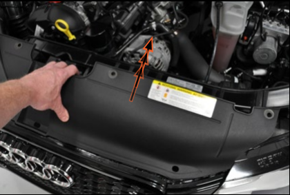
Step 4:


Locate the plastic guard above the LH CV shaft. Remove the two securing nuts, then pull it forward, pivot it around the CV shaft, and remove it.
Step 5:
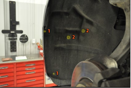

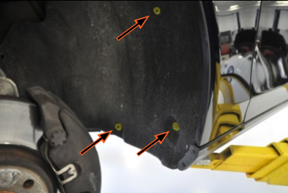
The LF fender liner needs to come out next, and it’s held in place by a number of different fasteners. We’ll point them all out over the next few steps.
In this step, remove the two forward screws
(1) at the edge of the fender, then using a pick remove the two clips
(2) just to the right.
Step 6:


Remove the expanding rivet that holds the fender liner to the body. It’s located just forward of the CV shaft. The expanding rivet will come out in two pieces, center pin first, then the rivet body.
Step 7:
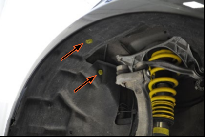

Remove the two clips on the top side of the fender liner, forward of the suspension strut.
Step 8:

Finally, remove the three rearward fasteners consisting of one nut and two clips. Now carefully pull the fender liner out from the lip of the fender, then downward, and remove it from the car.
Step 9:


On the RH (passenger) side, remove the two forward fender liner screws at the edge of the fender. It is not necessary to remove the fender liner or the wheel on this side.
Step 10:


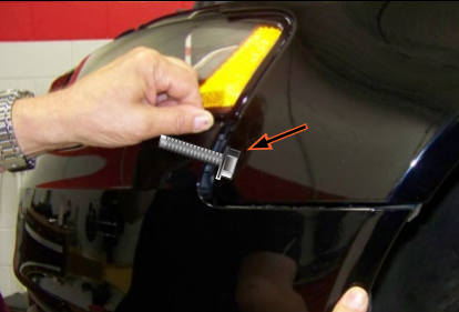
On both sides, reach in behind the bumper and disconnect the fog lamps (LH shown).
Step 11:


Remove the four screws along the rear edge of the lower radiator shroud.
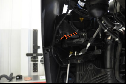
Step 12:

Inspect the side view of the bumper cover/fender on the right. There is a bolt on each side that secures the bumper cover to the fender. We have overlaid the bolt in this illustration so you can visualize its location.
Step 13:

Remove the bolt on each side that secures the bumper cover to the fender (see the illustration in step 12). On the RH side, you can access the bolt by pulling back the edge of the fender liner.
Depending on model and production date, your vehicle may have two bolts on each side that will have to be removed prior to pulling off the bumper cover.
Step 14:
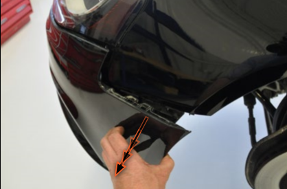

Pull out on both rear edges of the bumper cover as shown to release them from the clips on the fender.
Step 15:

Remove the four upper radiator shroud screws.
Step 16:

Lift up on the rear edge of the radiator shroud, then pull it rearwards to unhook it from the grille, and remove it.
Step 17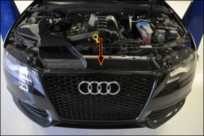

Look down between the grille and radiator and disconnect any components that are attached to the back side of the grille.
Depending on model, you may find the following:
- Homelink Transmitter
- Ambient Air Temperature Sensor
Step 18:


Remove the two screws at the top corners of the grille.
Step 19:


Remove the bumper cover by pulling it straight forward. It’s not heavy but slightly awkward. If you’re careful you can balance it in the middle, but it’s much easier if you have a friend help you with it.
Step 20:


With the bumper cover removed, we’re ready to start on the charge pipes. Let’s start with the turbo outlet pipe. Loosen the hose clamps on the original turbo outlet hose at the turbo damper on one end, and the intercooler inlet on the other. Pull the hose off and remove it.
Step 21:
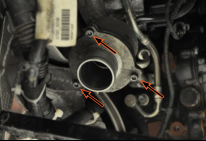

Remove the three screws on the original turbo damper, and remove it from the turbo outlet. Be careful not to lose the small o-ring seal between the two.
Step 22:


Thoroughly clean the o-ring and the seal groove, then install the o-ring into the groove on the turbo outlet, using light grease to hold it in place.
Step 23:
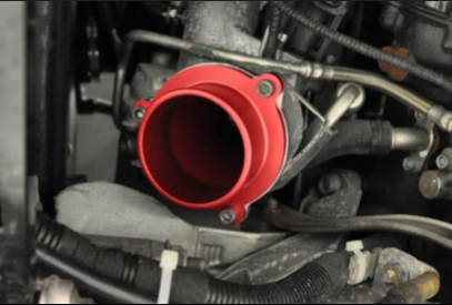

Install the new turbo outlet adapter using the original screws.
Step 24:
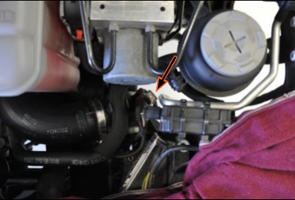

Now let’s move on to the intercooler outlet and throttle body pipes on the LH side of the vehicle. Look down in front of the ABS pump, locate the MAP sensor (on the top end of the intercooler outlet pipe) and disconnect it.
Step 25:
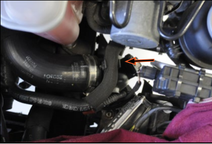

Pull the power steering hose out of the clip on the top end of the intercooler outlet pipe.
Step 26:
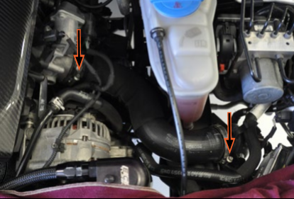

Loosen the hose clamp on each end of the original throttle body hose.
Step 27:


Pull the throttle body hose off each end and remove it from the car.
Step 28:


Loosen both hose clamps on the original intercooler outlet hose, then pull it off both ends and remove it.
Step 29:


Pull the power steering hose out of the clip on the side of the intercooler outlet pipe.
Step 30:


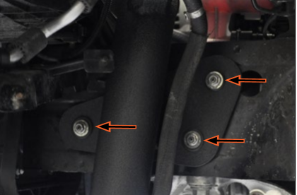
Remove the three mounting nuts, then remove the original intercooler outlet pipe from the car.
Step 31:
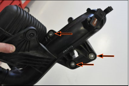

Remove the three mounting bushings from the original intercooler outlet pipe in the following manner:
- Slide out the metal sleeve washer from each one
- Pull the rubber bushings out of the intercooler pipe bracket
Each of the three bushings is a different size and only fits in its corresponding location.
Step 32:


Install the original bushings and sleeves into the new intercooler outlet pipe bracket.
Note the different size and shape of the mounting holes in the bracket. Make sure each of the three bushings is installed in its correct location.
Step 33:


Remove the two screws, then carefully remove the MAP sensor from the original intercooler outlet pipe.
Step 34:


Install the MAP sensor into the new intercooler outlet pipe using the new screws provided with the kit.
If you have purchased the complete kit and are installing a new ECS Tuning intercooler, skip to Page 35 to install the intercooler at this time.
If you are installing the charge pipes only, continue on the next page.
Step 35:


Loosely place a hose clamp onto each end of the correct silicone coupler for the intercooler you are using (see below), then push the coupler onto the intercooler outlet.
Stock Intercooler:
Coupler: 2.5” to 2.25” Reducing, small end located on intercooler.
Clamps: 60-68mm located on intercooler side, 67-75mm located on pipe side.
ECS Intercooler:
Coupler: 2.5” Straight.
Clamps: 67-75mm on both ends.
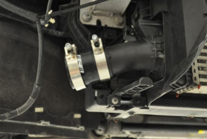
Step 36:
Install the new intercooler outlet pipe into place, pushing it into the coupler on the bottom and over the studs on the frame.
Step 37:
Install and tighten the three nuts on the intercooler pipe bracket.
Step 38:

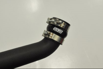
Tighten both the T-bolt clamps on the silicone coupler.
You may position these clamps as desired to achieve the look you want.
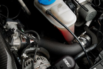
Step 39:


Reconnect the MAP sensor.
Step 40:

Loosely place a 67-75mm hose clamp over each end of one of the silicone hump couplers, then push it onto the top of the intercooler outlet pipe.
Step 41:
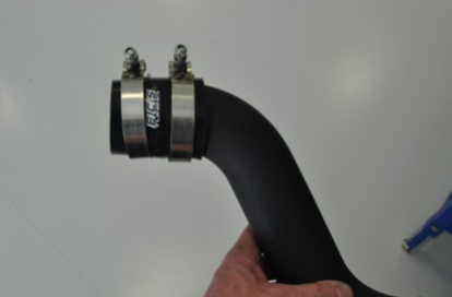

Push the straight coupler onto one end of the new throttle body pipe, then loosely place two 67-75mm clamps over the coupler.
The throttle body pipe is the same on both ends and can be installed in either direction.
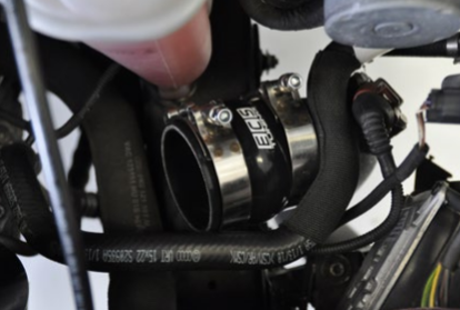
Step 42:
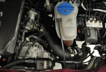

Install the throttle body pipe into place.
Step 43:

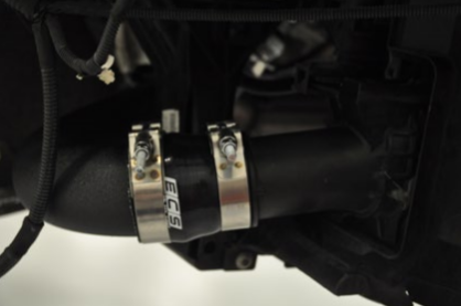
Make sure both silicone couplers are aligned properly, then tighten all four T-bolt clamps.
You may position these clamps as desired to achieve the look you want.
Step 44:
Now, moving back to the turbo outlet pipe, loosely place a hose clamp onto each end of the correct silicone coupler for the intercooler you are using (see below), then push the coupler onto the intercooler inlet.
Step 45:

Inspect the new turbo outlet pipe and identify the ends. The turbo end has a 60 degree bend on it while the intercooler inlet has a 123 degree bend.
Step 46:
Slide the remaining hump coupler over the “turbo” end of the turbo outlet pipe, with two 67-75mm clamps loosely installed.
Step 47:

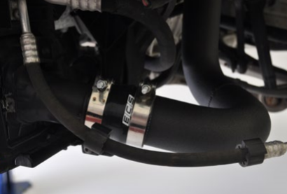
Install the new turbo outlet pipe into place, routing it over the core support brace.
Step 48:

Push the turbo outlet pipe up into the hump coupler, then tighten the clamps. make sure that the pipe does not hit the brace.
Step 49:
Tighten the two T-bolt clamps at the intercooler.
Step 50:
Reassemble the vehicle:
Reinstall the bumper cover.
Reinstall the fender liner
Reinstall the skid plate/insulation Panel
Install and torque the LF wheel to 120 Nm (89 Ft-lbs).
Your Charge Pipe installation is complete!