
The B8 A4 is a wonderful example of both luxury and performance but it isn’t perfect. As we mentioned in our last article about the common issues known to B8 A4 2.0T models, there are a few inherent flaws that need addressing for long-term reliability to be assured. As with any modern car, the crank case ventilation system routes pressure buildup through the intake to be burned off in the combustion cycle. You can read more about it in our article that describes how catch cans work. Effectively, we need to intercept that pressure release to prevent oil from burning off in the combustion cycle, as a proper catch can will trap those particles for cleaner operation of the engine and reduced oil consumption. This is our step-by-step instruction manual on how to install the ECS Baffled Catch Can in your B8 A4 2.0T with the plastic intake manifold.
Step 1:
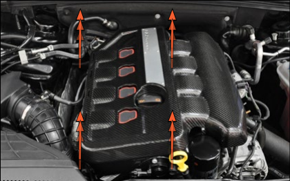
Begin by removing the engine cover. Whether you have the factory cover or our carbon fiber engine cover as shown here, they are both removed by pulling up at the four corners to release the rubber grommets.
Step 2:
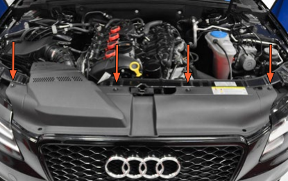
Remove the four upper radiator shroud screws (some vehicles may have push pins/expanding rivets).
Step 3:
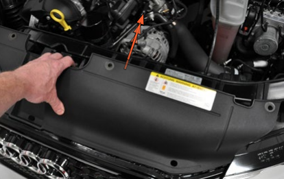
Lift up on the rear edge of the radiator shroud, then pull it rearwards to unhook it from the grille, and remove it.
Step 4:
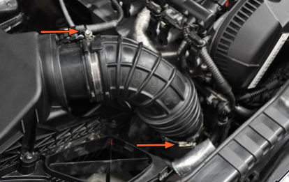
Remove the two air scoop hold down screws.

Step 5:
Pull up on the air duct where it meets the air box and remove it along with the air scoop.

Step 6:
Remove the turbo inlet hose by loosening the two clamps and pulling it off at both ends.
Step 7:
Locate the Mass Air Flow (MAF) sensor connector

Step 8:
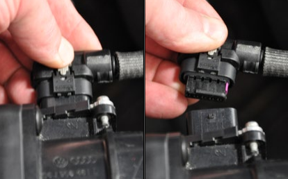
Unlock the connector on the MAF sensor by pulling the gray locking tab out until it stops.

Step 9:
Press down on the end of the gray locking tab, then pull the connector off the MAF sensor
Step 10:
Pull up on the airbox on both sides and remove it from the engine compartment.

Step 11:
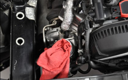
Cover the turbo inlet with a clean rag to prevent anything from falling into it during the installation.
Step 12:
Remove the crank vent hose by disconnecting it from the intake manifold and PCV assembly. The diagram below explains how to release these squeeze-lock fittings.

Normal Installed State: The tabs keep the hose “locked” in place.
To Remove: Squeeze the knurled sides of the locking ring together and the tabs will expand out and unlock, allowing you to remove the connector.
Step 13:
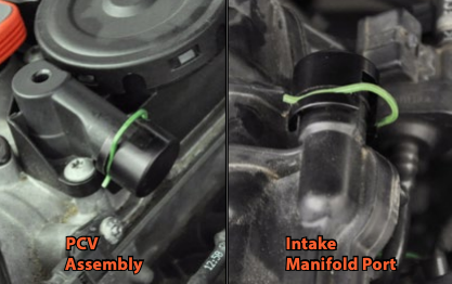
Lubricate the o-rings on the PCV caps with clean engine oil, then push one onto the end of the PCV assembly and one onto the intake manifold port.
Step 14:
Install a retaining clip into the groove of each PCV cap.
Step 15:
Occasionally, the PCV assembly outlet will have a lip on it that will interfere with the installation of the PCV cap. If you find this on your car, file the lip off until it is flush with the rest of the outlet, then install the cap as normal.

Step 16:
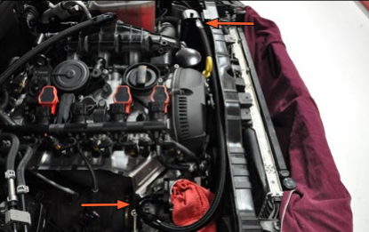
Remove the coil harness retaining bolt.
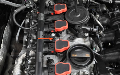
Step 17:
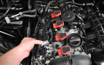
Disconnect the camshaft adjustment actuator connectors. There are eight of them, and these connector locks operate the same as the MAF sensor connector.

Step 18:
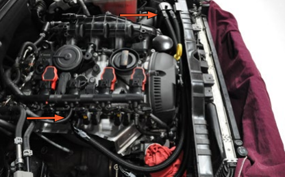
Press the release tabs to unlock all 4 coil electrical connectors.
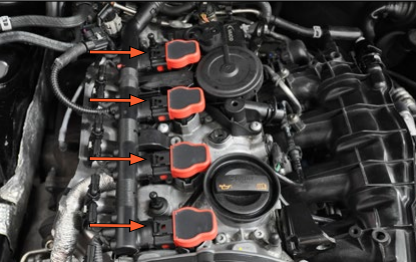
Step 19:
Pull the ignition coil harness completely off of the coils.
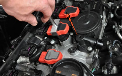
Step 20:
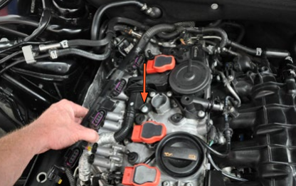
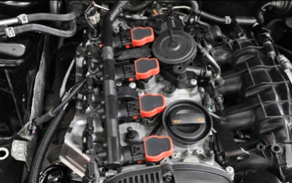
Remove the #3 ignition coil by pulling it straight out.
Step 21:
Remove the PCV adapter retaining bolt.
Step 22:
Pull the PCV adapter out of the PCV assembly.

Step 23:
Remove the two screws securing the breather tube to the turbo housing.
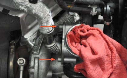
Step 24:
Remove the breather tube.

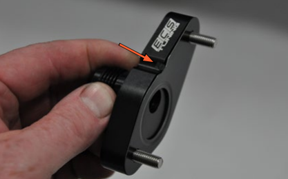
Step 25:
Place the new breather tube gasket onto the turbo adapter plate, then thread two of the new M6 x 16 screws through the plate and into the gasket. Note that the tab on the gasket aligns with the cutout in the adapter plate.
Step 26:
Install the turbo adapter plate onto the turbo housing and tighten the screws.

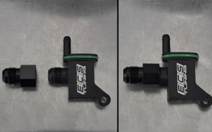
Step 27:
Install and tighten the -10 AN extender onto the PCV adapter. It is only necessary to tighten these by hand using a crescent type wrench.
Step 28:
Lubricate the seal with clean engine oil and slide the PCV adapter into the PCV assembly, then install and tighten the retaining bolt.

Step 29:
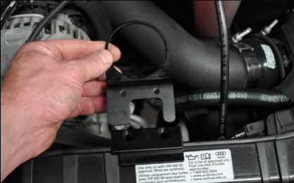
Place the bracket mounting plate onto the lip of the radiator core support in the location shown.

Step 30:
Slide the catch can bracket underneath the radiator core support so the screw holes in the bracket are lined up underneath the holes in the bracket mounting plate. (Reference step 35 for a side view to make sure you have the bracket correctly installed).
Step 31:
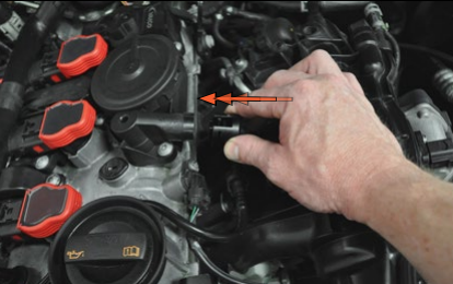
Loosely install the remaining two new M6 x 16 bolts, then push the bracket against the rib in the radiator core support (direction of arrow) and tighten the bolts.

Step 32:
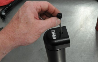
Unthread and remove the dipstick from the catch can.
Step 33:
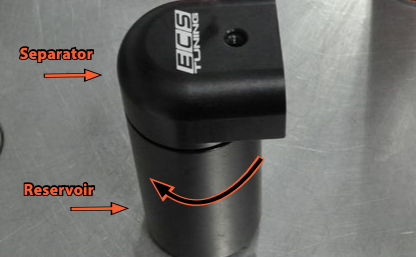
Unthread and remove the catch can reservoir from the separator.
Step 34:
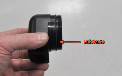
Using clean engine oil, lubricate the o-ring seal that is located in the groove of the separator.
Step 35:
Place the separator into the catch can bracket.

Step 36:
Thread the reservoir onto the separator but do not completely tighten it at this time.

Step 37:
With the new catch can in its installed position, note the locations of the feed and return side of the separator.

Step 38:
Install the return line in place between the catch can and the turbo adapter plate and tighten both fittings.
Step 39:
Install the feed line in place between the catch can and the PCV assembly adapter and tighten the fittings.
Step 40:
Perform the following:
Install the #3 ignition coil
Connect the ignition coil harness
Install the ignition coil harness bolt
Connect the camshaft adjustment actuators
Lubricate the catch can dipstick seal with engine oil and install it into the catch can.
Step 41:
Install the two line separators in place where the lines run between the front of the engine and the radiator core support.

Step 42:
Rotate the catch can so it is parallel with the edges of the bracket, then fully tighten the reservoir to lock it in place.

Wrapping Up
With the catch can installed, you know that only clean, fresh, air is fed through the intake to the combustion chamber. This will help improve your engine’s efficiency and will provide an improvement to your B8 A4’s dependability. Don’t forget, though. With the addition of a catch can you will need to drain it periodically and monitor how much oil is trapped in the can. If you live in colder climates, it is recommended that you drain the can weekly to prevent any condensation in the can from freezing.