The Porsche Cayenne in the late 90s and early 2000s did what Lamborghini could not do in the 1980s. Their high-performance, luxury, sport utility vehicles were praised as capable off-roaders, family haulers, daily drivers, and exceptionally well performing touring cars. Like all pioneering, however, they were not without some early problems as Porsche adopted a V8 platform to power the larger Cayenne. The Coolant Pipes beneath the intake manifold have a tendency to leak, as they are made from plastic on the 2003-2006 model Cayenne Turbo and Cayenne S. Today, with the help of my good friends in our Research and Development department, I will walk you through exactly what it takes to replace and upgrade your coolant tubes as either a preventative measure or repair that you may desperately need.
First, here is a list of all the tools you will need to complete the job. If you don’t have something, the links provided will take you straight to that tool to make sure you have everything necessary before you start your project. Keep in mind, this is a fairly involved DIY project, but not one that demands a high skill level or familiarity with mechanics. If you have all the proper tools for the job and follow this instruction guide, you can confidently tackle this service at home in your garage.
Porsche Cayenne S/Turbo Coolant Pipe Upgrade Kit
Required Tools:
- Fuel Line Pliers (ES1306816)
- Coolant Drain Pan
- T40 Torx Driver
- E10 Torx Socket
- Ratchets/Extensions/Swivel
- Torque Wrench
- Clean Towels
- Cooling System Pressure Tester
- Refractometer
- Manual Fluid Extractor
- Schwaben Coolant Evac Tool Kit
- Spring Clamp Tool
- 12mm Triple Square Socket Driver
- 16mm Socket
To drain the coolant, you will want to raise the car up. As well, when bleeding the car if you choose to do so without a coolant purge tool, you will want to have the bleed point be the highest point of the car so the front end will need to be raised. Here is a diagram for you to check your lifting points and secure the vehicle properly.


Make sure to disconnect your battery, as you will be working close by and do not want to harm yourself or the car.
Tool Tips
Next, these tools we mentioned earlier are going to make your life much easier. Here are a few of our tips:

The Schwaben Locking Hose Clamp Pliers allow technicians to access the flat-type hose clamps located in hard-to-access areas. The pliers have a locking mechanism to hold clamps in the open position, making the removal and installation of clamps much easier.

The Schwaben Coolant Evacuation Tool Kit is used universally among all vehicles using the Venturi method to ensure that there will be no air pockets when refilling the cooling system and can help identify if leaks are present. Once you are sure the system is ready you can add your coolant with the opening of the valve after the pressure gauge reads 0 the system is filled.

A refractometer is the most accurate way to measure the specific gravity of the coolant mix to ensure proper freeze protection. Use the eyedropper tube to place a few drops of coolant on the sample window beneath the clear plastic cover, and peer through the eyepiece to see the exact water-to-coolant ratio and freeze protection, displayed on a numeric scale. Look for 34 degrees F, indicating a 50/50 mix. Remember, too much antifreeze is not a good thing. Never exceed a 60:40 ratio of antifreeze: mixing water.
Under the Hood
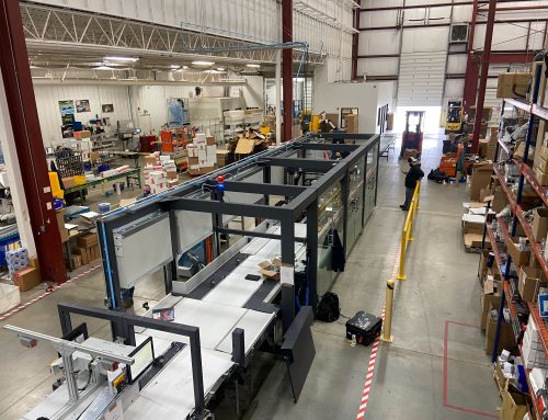
We’ll start you off with this bird’s eye view of the engine compartment layout. Take a few moments to familiarize yourself with major components and their locations as this will help you easily reference close-up shots throughout the DIY. The coolant pipes we are replacing in this tutorial are located beneath the intake manifold. The intake manifold is made of plastic and held in place by 10 fasteners. In addition to the manifold-throttle body assembly, we must also remove the front air intake Y-pipe and disconnect all sensors, fuel injectors, and fuel, vapor and vacuum lines attached to the manifold and throttle body. Refer back to this legend as needed to identify components and their locations.

This view shows the engine after the intake manifold is removed. Note the location of the three smaller coolant pipes and their installed location between the thermostat housing and rubber coolant hoses at the rear of the engine. Also, note the location of the breather hose included in your kit.

This image shows the engine with the smaller triple pipes removed. The large coolant pipe is located “one floor down,” beneath the triple coolant pipe array above it. The large pipe connects the thermostat housing to the coolant plenum that straddles the rear of the engine. Now that you have your bearings, let’s get started.

1) (Vehicles with air suspension only) If raising the vehicle off its wheels, Porsche recommends setting the suspension to service mode. Ignition on, push the rocker switch forward for 5-10 seconds until the service mode message appears in-dash display. The system will revert to normal operating mode, automatically, when you drive off. The owner’s manual contains a lengthy section on suspension operation and controls.

2) Disconnect the battery (located beneath the driver seat). The easiest way to do this is to pop off the carpeted cover from the front of the driver seat base to expose the front of the battery. Then unbolt the main ground strap between the battery and body.

3) Remove the front protective plastic shield beneath the engine to gain access to the radiator drain plug, located at the bottom right-hand side of the radiator. Drain the engine coolant by unscrewing the blue slotted-head plastic drain plug. Leave the radiator cap on as you first open the drain. Have a flexible drain funnel and large capacity drain pan positioned beneath the drain to capture the coolant. Open the drain, then loosen the recovery jug fill cap slowly. This will drain the coolant more slowly so you don’t have it everywhere! Then reinstall and hand tighten the drain plug. (Not too tight, snug will do!)

4) Back to the engine compartment. Remove the plastic beauty covers from the right inner fender area and cowl. Turn the slotted-head plastic bayonet retainers (arrows) a quarter turn to release them

5) Disconnect and remove the Secondary AIR injection pumps. Three bolts: T40 Torx driver and ratchet required. (We found that removing both pumps made extra elbow room.) Loosen the air pump retainer bracket bolts at the right side pump bracket. (E10 Torx socket and extension required.) No need to completely remove the screws or bracket. Just get the bracket loose enough so you can slide the right engine beauty cover out without scratching it.

6) Remove the engine torque rod. It is bolted to the right cylinder head and to a body bracket on the right inner fender. (12mm triple square driver, long-handled ratchet or breaker bar, and 16mm socket/ratchet required.)

7) Unbolt the vacuum pump support bracket above the inner torque rod mount, and pull it aside as we have done here. (Arrows point to bolts and mating holes in the bracket.) This exposes the inner torque rod mount. Unscrew the torque rod attachment bolt from the captive nut in the torque rod bracket using a 16mm socket and ratchet. Remove the torque rod; lay it aside.

8) Pop off the front-center engine beauty cover above the throttle body (ball stud and grommet attachment only; lift upward, no tools required). Remove the cylinder head plastic beauty covers (photo right), which are held in place by ball studs and grommets at the top, and by T27 Torx head bolts, one at each ignition coil.


9) Unplug the boost pressure sensor electrical connector at the top of the Y-pipe. Then squeeze the two lock tabs and disconnect the venturi tube (pressure pipe) elbow from the bottom of the Y-Pipe (Inset photo). Loosen the air inlet hose clamps (arrows).

10) The Y-pipe is attached to the throttle body with two plastic push pins. The pins engage grooves in the side wall of the throttle body. To remove the Y-pipe from the throttle body, we must first remove the pins, and then pull the two components apart, as we have done here.

11) The plastic pins have a locking tab at the bottom that you cannot see when looking down from the top with the Y-pipe installed on the engine. To remove the pins, align the small mark on the head of each lock pin with the external groove in the pinhole, as shown. Then pull each pin straight up with pliers to remove it. Do not try to unscrew the pins or you will break off the lock tabs.

12) With the pins removed, pry the Y-pipe rubber hoses off the air inlet tubes; remove the Y-pipe.


13) Disconnect all vacuum lines, crankcase ventilation hoses, and electrical connectors at the throttle body. There are quite a few connections clustered around and connected to the throttle body; note how things come apart (or take a few more digital photos of your own) so you’ll know how it goes back together.

14) Treat the plastic locking tabs on the electrical connectors with care; they are probably heat-hardened, brittle, and will break easily if stressed. The release tabs on this throttle motor connector are very small, and we compress them carefully as we remove the connector.

15) Disconnect the crankcase ventilation hoses and check valve from the engine and intake manifold (arrows show connections). There are several plastic hose connectors used on the engine. Squeeze the circular ring around each connector (arrows) to release the locking tabs and pull the hoses off.


16) Disconnect the two fuel line connections located at the front of the cowl tray, just above the rear of the intake manifold. (See our master illustration for location.) You’ll need 17 and 19mm open end wrenches. Catch the small dribble of fuel from the line in a shop rag.

Compress the release tab on the right side fuel line and disconnect it.

17) Disconnect as many of the fuel injector electrical connectors as you can reach easily. (We’ll come back for the tough ones after the manifold is unbolted and raised slightly, giving us better access.) Each connector has a wire retainer clip. Push against the spring clip to compress it as you remove each connector from its injector.

18) Loosen the T40 Torx intake manifold bolts (10 bolts total). The bolts will rattle around inside their holes in the manifold when fully loose, but will not pull or fall out of the manifold.

19) The rear manifold bolts are a little tougher to reach. Grab a swivel socket and extension to loosen them.

20) With all manifold bolts unscrewed fully, raise the front of the intake manifold just high enough to access and unplug the remaining fuel injector electrical connectors. Then pull the manifold forward just far enough to disconnect the vapor and vacuum lines at the rear of the manifold. Remove the manifold from the engine.

21) Here’s the view from the rear of the manifold. (Arrows 1 and 2 points to the disconnected vacuum lines, and arrow 3 points to the manifold venturi tube port.) Remember these locations when we reinstall the manifold. Disconnect the venturi tube from the Y-pipe. This is the other end of the tube removed from the Y-pipe in step 9. Squeeze the release tabs and pull. Be careful, that tube on the manifold is plastic, too!

22) Immediately apply masking tape over the intake ports in the heads. Wide painters masking tape worked well for us and came off cleanly during reassembly Caution: With the ports taped, take a vacuum cleaner and remove accumulations of dirt and sand. (This engine even had a world-class rodent nest next to the starter.) The plastic pipes we’re replacing, including the thin coolant return line, are highlighted.

23) Install the new gaskets on the intake manifold. The new gaskets have a raised sealing rib that pushes into mating grooves in the manifold to hold them in place. Use no glues or sealers. Cover the manifold port openings to keep out debris and foreign objects, and lay it aside for now.

24) Unbolt the plastic hose retainer at the rear of the engine (three bolts; E10 Torx socket and extension). Unclip the wire loom retainer loops from the convoluted tubing. Pry the top and bottom sections of the retainer apart with a screwdriver. Remove the upper section of the retainer. (A new retainer and new bolts are included in your kit.)

25) Remove the plastic coolant pipes. Expect to do some wiggling and prying here. Our old plastic pipes came out hard. Check the holes the old pipes vacate in the thermostat housing. (This photo is shot from the rear of the engine looking forward.) Our replacement coolant pipe trio seals inside these holes with o-rings, so get things super clean before installing the new pipe assembly.

26) The only way to remove the large plastic coolant pipe is to cut it in pieces and take it out in chunks. Cut a hole in the top of the pipe (arrow). Suction out any remaining coolant or you will have a mess in the engine valley. Using a saw or cutting wheel of choice, section the large plastic pipe and remove it.

27) The large aluminum replacement pipe comes in two pieces so you can install it without major engine disassembly. There is a stub pipe that fits into the rear coolant plenum, and a longer section connected to the thermostat housing. Once installed, the two sections are aligned and connected with a rubber hose coupler and clamps.

28) Clean the bore in the rear coolant plenum. Lube the o-rings on the stub pipe with the o-ring grease in your kit, and slide it into the smooth bore in the rear coolant plenum.

29) Prepare the longer large aluminum coolant pipe. Lube the inside of the rubber coupler hose with fresh coolant. Slide the rubber coupler hose over the end of the long tube until the metal tube and hose end are flush. Slide the two hose clamps over the pipe, but leave them loose.

30) Lube the o-rings with the lube in the kit. Install the end of the long pipe with the o-rings into the coolant bore in the thermostat housing. Make sure it goes in straight.

31) Push the large pipe all the way into the bore in the thermostat housing. Here, the pipe is installed, but not yet aligned with the rear stub pipe.

32) Rotate the pipe in its bore until its open end aligns with the stub piece. Slide the rubber coupler hose on to the stub piece; position and tighten the hose clamps. Rotate the clamp heads slightly to the sides so they don’t stick up in the air, or they may interfere with the triple pipe when we install it next.


33) Prepare the new aluminum triple pipe; lube the o-rings. Insert the triple pipes into the bores in the front plenum. Tap them into the bores using a soft-headed mallet. Ours were a very tight fit and needed to be helped along with small pry bars inserted between the metal bosses on the pipe assembly and the face of the rear plenum.

34) The plastic hose retainer in the upgrade kit comes in two pieces, with metal spacers and new attachment bolts. Slide the lower half of the retainer beneath the triple pipe. Attach the rubber hoses and clamp them in place. Align the three holes (arrows) in the retainer base with the threaded holes in the rear coolant plenum. The retainer: 1) Bolts to the engine and clamps around the aluminum pipes to hold them in place. 2) Supports the wiring harness convoluted tubing.

35) Install the new breather pipe included in your kit. Snap the elbows over the ports in the engine, and connect the small rubber hose at the rear (arrows). Make sure the lock clips snap in place at the front elbows (lower arrows).

36) Install the top section of the hose retainer. Make sure the breather hose attached in the last step is routed as shown (1). Secure the wiring harnesses in the loops (2). Align the upper and lower retainers. Insert the three metal spacers from the kit in the retainer bolt holes. Bolt the assembly to the engine, using the three new Torx bolts included in your kit (3).

Stop! All pipes and hoses are now installed and connected. Before proceeding, test the cooling system for leaks. Do this before reinstalling the intake manifold. You do NOT want to find a leak after the intake manifold is installed!
37) Cooling System Testing Here, we have pulled a vacuum in the cooling system, then closed the control valve to trap the vacuum. We will wait several minutes to see if the vacuum holds.

38) Don’t be alarmed if the hoses are sucked flat like the one in our photo. That is supposed to happen. Put your coolant in a clean bucket. When you are ready to refill the system, insert the fill tube into the bucket, and let it suck fresh coolant, filling the cooling system completely, with no air pockets. Filling the system by pouring coolant into the coolant recovery bottle is more time consuming, and may require repeated bleeding to purge all air from the cooling system.

39) As a final precaution, we pressure test the system. Porsche recommends a test pressure of 1.5 bar (22 psi). If you do not have a dedicated Porsche cooling system tester adapter that screws on to coolant recovery jug, use a universal adapter, available from aftermarket sources.

40) If the cooling system is leak-free, reinstall the intake manifold.
- Remove the protective tape from the intake ports.
- Position the intake manifold between the heads.
- Slide it back, towards the firewall, leaving enough room to reattach the vacuum lines and venturi line at the rear of the manifold. (See step 21 for the photo.)

Torque Spec Chart:
- Intake manifold to cylinder head M6 10Nm (7.0), then 15Nm (12)
- Engine torque arm on the bracket and on body 60Nm (44)
- Secondary AIR pump bolts 10Nm (7.5)
- Battery ground cable to chassis bolt 20Nm (15).
- Cylinder head beauty cover screws at coils 4-5Nm (3-3.5)

Reinstallation:
- Reattach all eight injector electrical connectors. Make sure the lock wires snap in place completely
- Slide the manifold into its normal installed position. Screw all 10 manifold bolts into their holes, but leave them loose until all are fully threaded.
- Cross-tighten all manifold bolts to 7.5 ft-lb; then final torque to 12 ft-lb.
- Reattach all hoses and connectors at the throttle body.
- Reinstall the Y-Pipe. Position the hoses routed beneath the Y-pipe carefully. Make sure they are secure in the plastic retainer or they may rub on the front of the engine.
- Replace the cylinder head beauty covers.
- Re-tighten the right side air pump bracket (E10 torx socket and extension) and reinstall both Secondary AIR pumps. Reconnect the air pump rubber hoses and electrical connectors.
- Reinstall the torque rod. • Reinstall the vacuum pump/bracket above the inner torque rod bracket.
- Replace the beauty covers above the coolant jug and at the cowl.
- Reconnect battery negative cable and replace the carpeted battery cover on the front of the driver seat base.
- Test drive and check for leaks. Using the refractometer, double check coolant specific gravity, looking for a 50/50 coolant water mix and freeze protection to -34 degrees F. This completes our coolant pipe replacement.
Cayenne S and Cayenne Turbo Coolant Pipe Replacement and Upgrade
Find the rest of your Porsche parts to keep your Cayenne running strong right here at ECS Tuning!