Overview
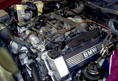
Our 1998 BMW 540i comes to us with over 200,000 miles on its odometer. It looks and runs like a car with far fewer miles, but has developed multiple valve cover gasket leaks. In recent days, it has also experienced intermittent engine misfire, a condition detected by the OBD monitoring system, which has dutifully stored a trouble code and illuminated the dashboard warning light.
There is a production split in 9/98 that results in two different valve cover gasket kits for this engine. Gaskets and fastener grommets are available individually, but we think you’ll agree that it is wise to “kit” this job so you don’t have to do it twice.
Other Considerations
Our M62 has coil-on-plug ignition. Each spark plug has its own coil, connected to the spark plug by a metal conductor encased in a rubber insulator.
We know before we start that if the valve cover gaskets on our M62 are leaking externally, there’s a very good chance they are also leaking out of sight at the inner seals surrounding the spark plug/coil wells.
Service Tip: Even if the coil connector boots are not oil-soaked and swollen on your high-mileage M62, we suggest you consider replacing them and installing a fresh set of spark plugs at the same time. Heat-hardened rubber boots can crack. The break in the insulator rubber lets secondary spark arc over to the cylinder head, causing a misfire, most noticeable during cold starts and loaded acceleration when spark secondary voltage spikes.
Before You Start
Spark plug R&R is a no-brainer. Right?
Perhaps.
Here are some things to consider when you install fresh plugs.
- Remove all liquid from the plug recesses in the head before removing the spark plugs. (We blew a lot of oil out of the plugs wells in this car.) Liquid oil is not compressible. If enough liquid gets into any combustion chamber, severe engine damage will result.
- Due to the design of the spark plug holes, the last plug thread at the electrode end can collect a ring of carbon. This black band of soot hardens and can make plug removal di cult. Scary, even. Be patient. If you break the plugs loose but then find them hard to turn, work them back and forth as you remove them to break up the carbon so it doesn’t damage the threads in the cylinder head.
- We do not use thread lube on plugs. Thread lube or anti-seize com- pound can run down the plug when hot and contaminate the electrode, grounding tabs, and porcelain. Name-brand plugs are now treated with a special thread coating, and most OEMs recommend against using extra lube.
- Think you know how tight to make the new plugs? This is one of the many places where proper torque really matters. Plugs have to be tightened correctly to seal properly, and also to transfer heat to the surrounding cylinder head. Please don’t guess. Torque plugs to spec.
First time doing one of these? It pays to clean o a horizontal surface and lay out all your parts as you remove them so you can inventory nuts and washers at a glance. Remember, the valvetrain and timing chains are all exposed while the covers are off, so for peace of mind it’s nice to know where all 22 cap nuts and their mating washers are at, before your reinstall the valve covers.
A spark plug socket and torque wrench will do a great job of tightening the plugs correctly. If you service these engines on a regular basis you’ll appreciate the convenience of a calibrated plug socket adapter, pre-set to the correct torque.
Installation
Step 1
Raise the hood.
The engine beauty cover is held in place by four plastic retainers that snap into a metal support bracket.
Press down on the center button in each retainer to release it as you pull upward on the cover.
Service Tip: Spraying the buttons with a light lubricant like WD40 washes away dirt and makes the buttons move more easily. Many will stick and be hard to press due to accumulations of dirt.

Step 2
Lift the beauty cover o the engine and lay it aside.
1) Pull the tee-head on the cabin air duct retainer strap to release it.
2) Rotate the curved cabin air inlet duct and remove it from the rewall.
3) Unplug the hood sensor
4) Pry forward on the wire bale that secures the cabin filter cover to the filter housing.

Step 3
Raise the front of the cabin filter housing cover and pull forward to remove it.
Then squeeze the wire clip at the front of the filter housing rubber mount, and lift the filter housing with filter up and out of the water tray.
Lay the cabin filter assembly aside.
Use a similar process to remove the right side cabin filter housing.

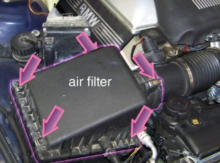
Step 4
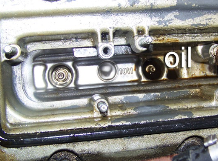
Remove the engine air filter cover. Located at the right front corner of the engine compartment, the filter lid is held in place by stainless steel spring clips (arrows). There is another at the inlet tube to the MAF (mass air ow sensor) tube that is not visible in this photo.
Service Tip: If you like extra elbow room, remove the lower filter housing as well; it’s held in place by a single 6mm bolt and a rubber push-mount. Removing it takes less than a minute, and it opens up the right front side of the engine for improved access.
Step 5
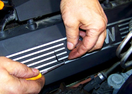
Remove the small trim covers from the valve cover beauty covers. There are two small, square covers per side.
Service Tip: Insert the tip of a small pick or tiny at-bladed screwdriver into the notch at the base of the trim covers and pry up to remove them.
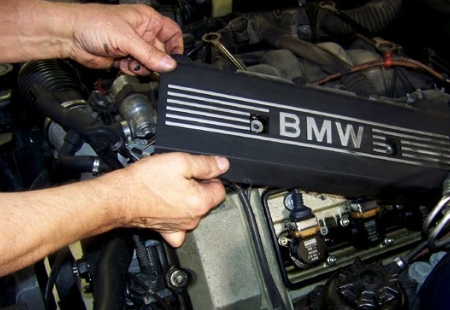
Step 6
Use a 6mm socket and ratchet to remove the two beauty cover retainer bolts, then lift the cover o the valve cover. Place the bolts with the covers to make them easy to locate later.
The process is the same for the left and right side valve cover beauty covers.
Step 7
Pry up and lift the clamshell cover over the battery jump start lug. Using a T25 Torx driver, remove the two screws holding the plastic cover to the top front of the left valve cover. Leave the mounting screws inside the box and snap the cover closed, that way they’ll be handy later.
Service Tip: The B+ box is the jump start connection. The large lug inside the box is connected directly to the battery positive terminal and is HOT (battery voltage) all the time. Assuming the plastic box is not damaged, simply closing it and laying it aside with the cable still connected should pose no problems, since the plastic cover is an insulator.

Step 8
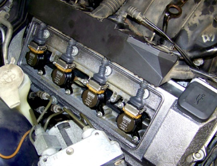
- Disconnect the ignition coils. (Pull the metal lock bar on each coil straight out to release it.) With the connector unlocked, pull straight up on the electrical connector to remove it from each coil.
- Unbolt and remove all the coils. No need to mark their locations; they are all the same part number.Service Tip: Note the location of the ground wire at one of the coil mounting studs on each bank. These braided copper wires (one per side) must both be reinstalled and properly tightened.Service Tip: If you have cylinder-specific misfire trouble codes, you may wish to mark the coils and reinstall them in the affected cylinders. That way you’ll have a starting point if new plugs and coil boots do not cure the problem.

Step 9
Inspect the spark plug wells on both sides after you remove the coils. If your gaskets have been leaking, the plug wells will contain engine oil.
Service Caution: Do NOT remove the spark plugs before cleaning out all the oil. The liquid inside the cylinders can cause severe engine damage.
Service Tip: If you have a way to suction out the oil, fine. If not, grab a shop rag (or two or three), and cover the wells. Wear eye and skin protection and insert the tip of your air nozzle into the wells and blast the oil up into the rag.

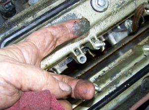
Step 10
To get things really clean, spray the wells again with aerosol brake cleaner, and repeat the process.
For comparison, the plug hole on the right is still swimming in oil, while the one to the left shows what a properly cleaned hole should look like: bright, clean, and dry.
Step 11
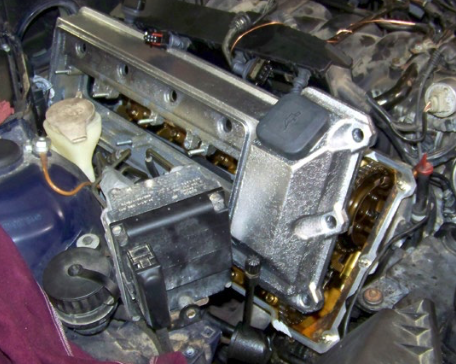
The electrical boxes above each of the valve covers impede valve cover removal.
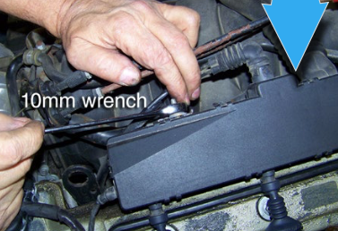
Using a 10mm wrench, loosen the 6mm nuts (two per side) that secure the electrical box studs to the fuel rail.
Service Note: These two black plastic boxes—one on
each bank—contain electrical wiring, including the injector and ignition coil wires and connectors.
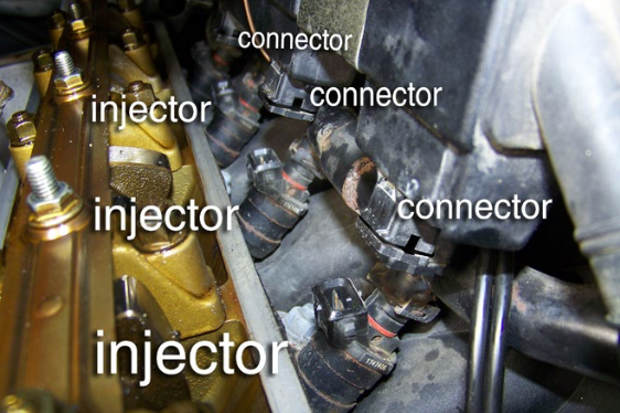
Now reach down with a long handled pick (or similar) and pry the wire clips off all eight injector connectors. Don’t waste time retrieving the clips one at a time, just let them fall next to the injectors. You can gather them later when the electrical boxes are out of the way. (See photo next page.) The rearmost clip on the right bank is pretty well hidden. If necessary, use a small mirror to guide the pick to the clip.
When all clips are removed, lift the electrical boxes straight up, o the injectors. Note: The rearmost connector on the left bank is not located in the main box; it has a short external wire harness and must be pulled o the injector separately.

When the covers are removed, retrieve the wire clips from the valley between the valve cover and the top of the intake manifold.

Reinstall all the clips immediately so they do not get lost. This also prepares the electrical boxes for re-installation.

As you lift the boxes the connector plugs will pull o the injectors. If the boxes stick, double check to be sure you have fully removed all the wire clips.
Step 12
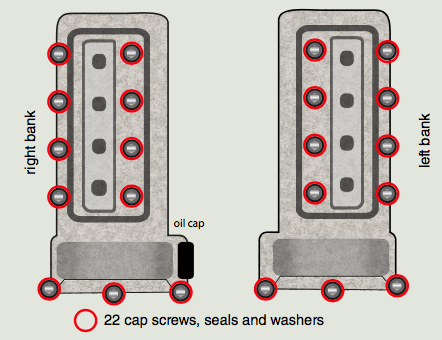
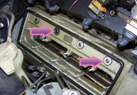
Using a 10mm socket, remove the cap nuts from the valve cover studs. There are 11 per side, 22 in all.
As you remove the cap nuts, keep track of the at washers beneath them. Lay nuts and washers aside in a safe place where they cannot fall into the engine when the valve covers are removed.
Step 13
Beneath each cap nut, there should be a flat washer (right arrow).
Beneath each washer, there should be a rubber grommet, shown here after the washer has been removed (left arrow).
The rubber grommets on high-milers may be very hard. You may have to take a pick or small screwdriver and pry them from the cover.
When all fasteners are removed, lift the valve cover o the mounting studs and remove it.
Valve Cover Removal Tips
There is no single right or wrong way to go about actually getting the covers o the car, but here are a few tips we hope you nd helpful.
- On the right side, the AC service pipe and brake lines on the ABS
unit may both be in your way. Both can be bent slightly to the side to make room. Just don’t get carried away. - Leave the old plugs in their holes for now so nothing can fall into them.
- Do not use a hard metal scraper to remove old gasket remover
or sealer from the top of the cylinder head. A plastic scraper and brake cleaner got our sealing surfaces shiny bright, without scoring the surface. - We were able to remove and install both covers without disconnecting any of the cables from the electrical boxes. It helped to have an assistant hold the wires and boxes up out of the way while we slid the covers beneath them.CAUTION: Plastic tabs and clips on older engines get extremely brittle. Prying on the electrical box cover clips to remove the box covers is like bending a soda cracker, so be warned.

One or more of the valve cover mount studs may screw out of the heads when you remove the cap nuts. If this happens, separate the cap nut from the stud, then screw the stud back into the head.

Don’t be surprised to find that the factory coating on the covers has turned into an ugly sludge, especially in areas that have been soaked in engine oil. We took no chances and sent the covers to a local parts store for soaking in a hot tank to get them really clean.
Step 14
With the valve covers clean and dry, check the gasket grooves
in both covers to be sure they are clean and free of any lingering gasket debris. Then press the new gaskets in, working them all the way into the grooves with your ngers until they are tight.
We do not add any lube or glue. If the covers are clean and true, the gasket will stay in place as you reinstall the cover.
Service Tip: The half moon seals are part of the outer gasket
and will align with the corresponding half moon openings at the rear of each head.

Step 15
Apply a dab of sealer at the top gasket sealing surface at
the spots where the cylinder head and front engine cover meet (arrows).
Service Tip: Do not apply too much sealer. This is a common mistake. You need just enough sealer to ll the tiny gaps between the head, front cover, and front cover gasket.
Service Tip: Elring Dirko sealant ES263904 is a good choice
for sealing this location. It is a permanently elastic, temperature- resistant silicone-based sealer. When applied properly to a clean surface, it skins in 5-10 minutes. By the time you complete the job, this sealer will be ready so you won’t have added down time waiting for it to cure.

Step 16
Pre-assemble the new grommets, washers, and cap nuts. This makes them easier to install on the head studs.

Step 17
Slide the covers into place. Be careful not to catch the gasket on any of the studs as you slide the cover in place.
Drop the cover holes over the studs, and screw all of the grommet/washer/cap nuts on by hand.
Step 18
Starting in the center, torque the valve cover fasteners in a star pattern, working from the center out.
Use a low range torque wrench set to 10Nm (7.5 ft-lb).

Step 19
If you haven’t already done so and are replacing spark plugs and/ or coil boots, prepare the coils.
As you can see, the rubber on the old spark plug boot connectors is soft and bloated from being immersed in oil.

Step 20
Pull the old boots straight o the end of the coils. Use brake cleaner and compressed air to wash away all oil residue.
When the coils are all cleaned, push the new rubber contact boots onto the coils. You should hear a faint click and feel the electrical contact retainer clip snap in place against the end of the coil when the boot is fully seated.
Replace the spark plugs using the tips on page 3 of this pdf.

Step 21
Install the coils.
Push the rubber coil boots over each plug.
The coil connectors in the boot are spring loaded, so push in as you start the nuts; torque them to 10Nm (7.5Nm). Don’t forget to reinstall the ground wire on each bank.

Step 22
Now it’s time to reinstall the electrical boxes.
- Align the connectors over the injectors. (Make sure the wire clips are installed.) Push down on the box until the individual connectors slide over the injectors and lock in place. You’ll hear them click when they lock.
- Plug in the coil connectors and push in on the metal bars to lock each one in place.
- Replace the two top nuts at each electrical box.
- Reinstall the beauty cover on the valve cover.
Step 23
- Repeat the process on the left side of the engine.Service Tip: Reinstall the battery B+ box on the top of the left valve cover before reinstalling the beauty cover. The B+ cable runs beneath the cover.
Finishing up
Service Tip: Before you finish, take a moment to check the air
inlet accordion duct connecting the air filter outlet to the throttle (arrow). We suggest you remove and inspect it for cracks, top, and bottom. Ducts commonly crack from repetitive exing and heat. Air leaks between the mass air ow sensor (MAF) and throttle make the engine run lean and reduce performance. Careful inspection showed that the duct on our car was indeed cracked and leaking. It was replaced.
Time to finish up:
• Reinstall the engine air cleaner assembly.
• Reinstall the cabin air filter housing assemblies.
• Reinstall the top engine beauty cover.
• Check and correct the engine oil level as needed.

Interested in purchasing?
Valve Cover Repair Kits