Installing ECS Tuning front and rear sway bars on your E9X BMW is a rewarding project that you will be able to complete in a weekend. Our step by step instructions will remove any guesswork and provide you with a smooth installation. Before you begin, read and familiarize yourself with these instructions and make sure you have all the required tools on hand. Even though you will not be altering any actual alignment adjustments, as with any type of suspension work, we recommend that you plan a four wheel alignment to keep your suspension fine tuned and to correct for any minor changes that may occur. Thank you for purchasing our ECS Tuning Sway Bars. We appreciate your business!
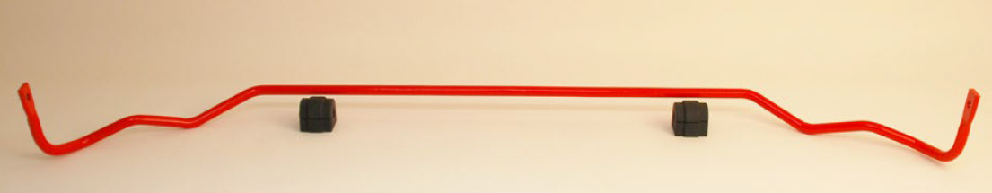
Front Sway Bar and Bushings

Rear Sway Bar and Bushings
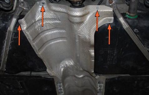
Safely raise and support the vehicle. Remove the front insulation panel
located directly beneath the engine
.
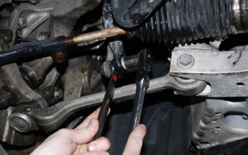
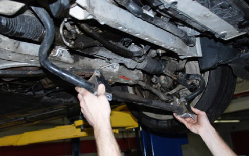
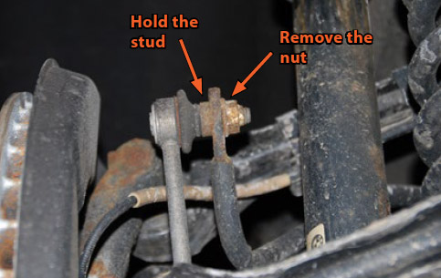
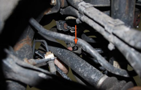
Hold the lower stud of each front sway bar link stationary with a wrench,
then remove both lower nuts from each link and pull the ends out of the
original sway bar.
Remove the two front insulation panel brackets (one screw holding each
in place).
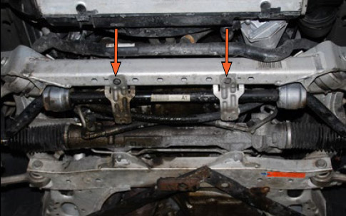
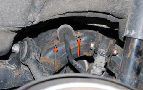
Remove the four nuts holding the front sway bar brackets in place (two on
each side).
CAUTION
Once all four nuts are removed, the sway bar will be loose and
ready to remove. Use caution so it does not fall off.

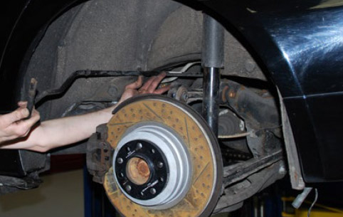
Using both hands, lower the front of the sway bar, shift it a few inches to
either side and remove it from the vehicle.
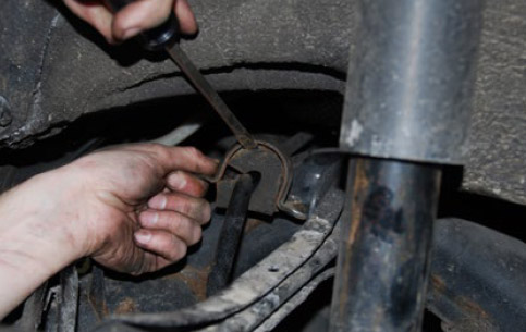
Insert a suitable tool through the sway bar bracket mounting holes for
leverage, then pry the sway bar brackets back and forth, alternating holes,
to remove them from the bushings.

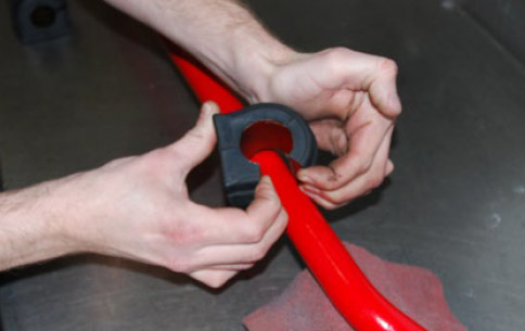
Spread each of the new front sway bar bushings by hand and install them
onto the new front sway bar.
Be sure to apply a thin layer of grease (included with the
sway bar) to the inside of each bushing. The “cut” or “open” side of each bushing can be placed on either side.
Lubricate the inside of each sway bar bracket, then press them down fully
onto each new sway bar bushing.

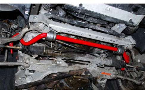
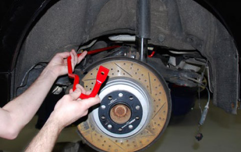
Install the new sway bar in place, rotating the bushings as necessary to
push the brackets onto the bracket studs. Make sure the ends of the sway
bar are located above the tie rods and lower control arms then install but
do not tighten the nuts onto the end of each stud.
Install the two lower end link studs into the sway bar and install the nuts.
Torque the end link nuts to 60 Nm (44 Ft-lbs). Torque the sway bar bracket
Mounting nuts to 21 Nm (16 Ft-lbs).
Install the front insulation panel brackets
Install the front insulation panel

Front Sway Bar installation is complete!
Safely raise and support the vehicle and remove the rear wheels.
For safety and convenience, we are using a wheel hanger to
support the wheel as we remove the lug bolts.

Hold both rear sway bar link studs stationary with a narrow spanner
wrench, then remove both link nuts and pull the link studs out of the rear
sway bar.
The original link studs require a narrow spanner type wrench to
hold them. If you do not have the appropriate wrench, locking
pliers may be used but be careful not to tear the link boot.
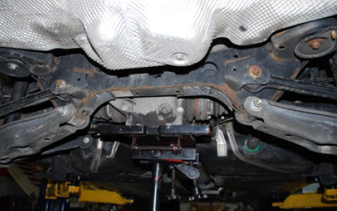
Remove the eight bolts and remove the center support plate.

Remove three of the four nuts holding the front exhaust pipes to the
catalytic converter flanges. Many of these nuts have been replaced and
the actual sizes may vary, but they are usually 12mm or 13mm. Loosen the
fourth nut, but leave it threaded on a few threads to support the front of
the exhaust until you are ready to remove it.

Pull the vacuum line off the exhaust valve on the LH rear.

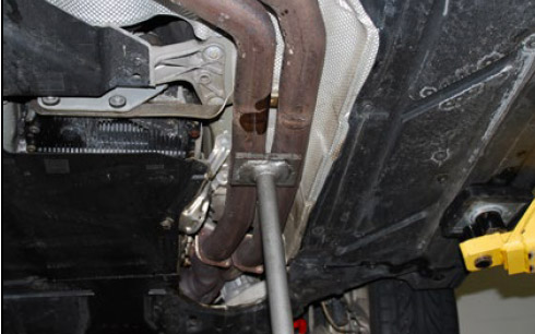
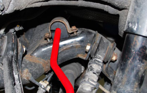
Remove the exhaust pipe support clamp located at the rear of the
transmission.

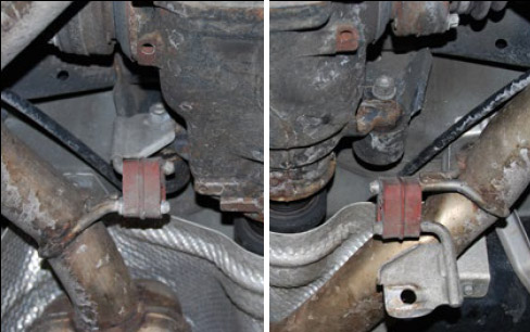
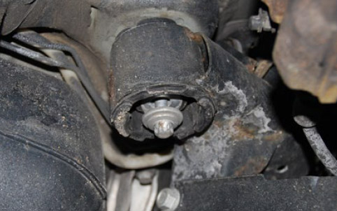
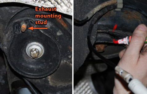
At the front of the rear differential, remove the two exhaust hanger
bracket nuts, pull the brackets off each side, then pivot them down out of
the way. Thread the nuts back on by hand.
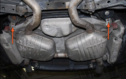
Remove the two rear exhaust hanger bolts.

Place a jack underneath the front of the exhaust system and remove the
last nut from the front exhaust pipe.
The exhaust system is very heavy. Before proceeding to the next
step, we recommend you enlist the help of a friend, or even two, to
lower the system.
Remove the two remaining exhaust mounting brackets and lower the
entire exhaust system from the car.
Remove both lower shock bolts on each side.

On the LH side only, remove the bolt securing the headlight level sensor
rod bracket to the LH rear lower control arm.
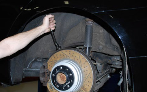
Place a jack underneath one of the lower control arms, then remove the
bolt that connects the lower control arm to the steering knuckle.
Raise or lower the jack as necessary to relieve tension on the bolt
before removing it.
Only raise the jack enough to relieve spring tension on the bolt. Be
sure not to lift the car and shift the weight on the lift or jack stands.

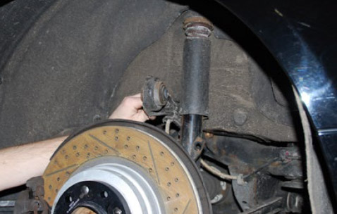
Slowly lower the jack until the control arm clears the steering knuckle and
shock absorber.

Relieve all tension on the jack, then pull down on the control arm with
one hand and remove the coil spring with the other.
Remove the coil spring on the other side (repeat steps preceding three steps).

Remove the three screws and one stamped nut and remove the rear heat
shield.
On both sides, remove the fasteners at the rear of the fender liners as
necessary to pull each fender liner back and access the connectors
underneath.

On the RH (passenger) side, disconnect the ABS and pad sensor
connectors, then let the wires hang down and allow the fender liner to
return back into place.

On the LH (driver) side, disconnect the ABS connector and let it hang
down, then allow the fender liner to return back into place.

Disconnect the headlight leveling sensor, then remove the sensor wires
from the plastic retainers on the subframe. Let the wires hang free.

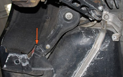
Remove the outer bolt at the steering knuckle for each upper control arm.
Each upper control arm will pivot up freely as shown.
Unhook the wiring harness retainers from each upper control arm, then
allow the harnesses to hang free underneath.
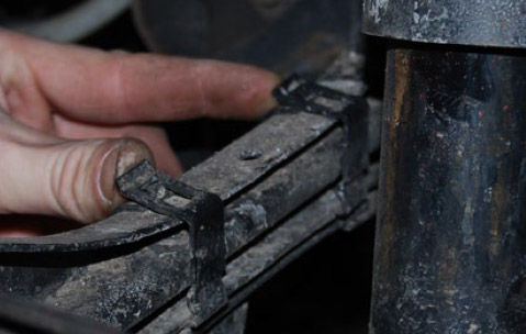
Locate the expanding rivet that secures the rear of the rocker panel trim at
the front corner of each forward subframe brace.
The expanding rivet works like this:
Figure A: The rivet pin is out allowing the fingers to compress and pass
through the hole in the subframe brace.
Figure B: The rivet pin is pushed into the rivet, keeping the fingers expanded
to a diameter larger than the hole in the subframe brace, preventing it from
backing out and keeping the trim securely in place.
To remove an expanding rivet you need to first remove the rivet pin. This
can be done by either pulling it out (if it protrudes and can be grabbed
with pliers) or using a small punch to push it all the way through.

Remove the expanding rivet on each side and pull the rocker panel trim
down to access the bolt underneath.
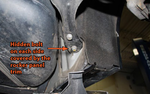
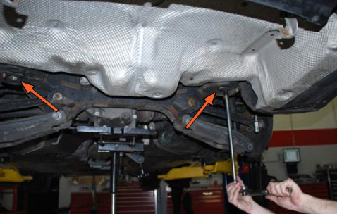
Remove the two 16mm subframe brace bolts on each side, then remove
each E18 subframe bolt. Remove the subframe braces, then thread each
E18 subframe bolt back in place, leaving them out approximately 1/4” to
1/2”.
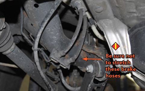
Do not leave these forward subframe bolts out. Be sure to
thread them in place as described. This will allow the subframe
to pivot as needed while keeping tension off of the brake hoses.
Make a reference mark between the rear subframe mounting plate and
the subframe. The M8 stud on the side of each mounting plate is for the
exhaust hangers (removed in step ten) and will need to be reinstalled
with the same orientation.
Securely locate a jack underneath the rear differential. Once the jack
contacts the differential, raise it just enough to put a slight amount of
tension on the differential mounts. This will keep the subframe tight
against the body when you remove the rear bolts.
Be careful not to lift the car and shift the weight on the lift or jack
stands.
Remove both rear subframe bolts.
Slowly lower the jack until the subframe has dropped down only about
three inches. This will give you all the room you need to access and
remove the rear sway bar.
As you lower the subframe, check to make sure that nothing is
binding or stretched, paying particular attention to the shocks and
the ABS and brake sensor wires.
Make sure that the brake hoses do not get stretched.
Remove the two rear sway bar bracket bolts on each side.
Carefully use a screwdriver to pry the brackets off of the original bushings,
then remove the bushings from the sway bar.
Remove the original rear sway bar using the following procedure:
Pull the sway bar a few inches out the LH side of the vehicle.
Make sure the sway bar is clear of the wires on the RH side.
Slowly pull the sway bar the rest of the way out from the LH side.
Place the sway bar on the ground, keeping the orientation the
same as it was when installing in the car.
Place the new rear sway bar next to the original, matching the orientation
so it will be correctly installed.

Install the new rear sway bar in place using the reverse of the procedure
which was used to remove it.
The new sway bar is thicker than the original. You may have
to lower the subframe slightly (approximately an additional
1/2”) to install the new bar.
Spread the new sway bar bushings and install them on the sway bar.

Lubricate the sway bar brackets and push them into place on each side.
Install all four bolts loosely at first, then thread them all the way in on each
side and torque them to 21 Nm (16 Ft-lbs).
The remainder of the installation is the reverse of removal, but for convenience and accuracy we have provided this step by step checklist, along with
torque specifications and special details as needed.
-
Raise the rear subframe up until it meets the body. Make sure no wires are caught or pinched.
-
Install both rear subframe bolts and mounting plates. Thread the bolts all the way in but do not tighten them at this time.
-
Remove the forward subframe bolts, install the subframe braces, reinstall the subframe bolts, then install the two brace bolts on each side.
-
Torque all four subframe bolts to 100 Nm (74 Ft-lbs).
-
Torque the subframe brace bolts to 47 Nm+90 degrees ( 35 Ft-lbs+90 degrees).
-
Reposition the rocker panel trim and install the expanding rivets.
-
Install the wiring harnesses onto each upper control arm.
-
Install the upper control arm bolts. Thread them all the way in but do not tighten them at this time.
-
Connect the headlight leveling sensor and install the harness into the retainers on the subframe.
-
Connect the ABS and sensor wires on each side and reinstall the fender liners.
-
Reinstall the heat shield.
-
Install the coil springs into place. Make sure the bottom of each coil spring is properly indexed in the lower control arm.
-
Raise the lower control arms using a jack until the shock mounts and control arm bolts can be installed.
Exhaust Hanger Brackets at Differential…………………………………..100 Nm (74 Ft-lbs)
Forward Subframe Brace 16mm Bolts (Always Replace)…47 Nm+90 degrees (35 Ft-lbs+90 degrees)
Forward Subframe E18 Bolts (Always Replace)………………………..100 Nm (74 Ft-lbs)
Front Sway Bar Bracket Nuts……………………………………………………..21 Nm (16 Ft-lbs)
Front Sway Bar Link Nuts……………………………………………………………60 Nm (44 Ft-lbs)
Lower Control Arm Bolts (Use New Nut)…………………………………..165 Nm (122 Ft-lbs)
Lower Rear Shock Absorber Mount Bolts (Always Replace)……60 Nm (44 Ft-lbs)
Rear Subframe Bolts…………………………………………………………………..100 Nm (74 Ft-lbs)
Rear Sway Bar Bracket to Subframe Bolts…………………………………21 Nm (16 Ft-lbs)
Rear Sway Bar Link Nuts…………………………………………………………….58 Nm (43 Ft-lbs)
Upper Control Arm Bolts (Always Replace)……………100 Nm+90 degrees (74 Ft-lbs+90 degrees)
Wheels…………………………………………………………………………………………120 Nm (89 Ft-lbs)
• A note about torque to yield or “stretch” bolts: Many bolts will have a torque specification listed in the format – xx Nm+xx degrees (xx Ft-lbs+xx degrees).
These bolts are torque to yield bolts, commonly referred to as “stretch” bolts. The correct procedure for torquing these bolts is: Stage One – torque them to
the Nm or Ft-lb specification. Stage Two – tighten each one the additional specified number of degrees. To prevent over-torquing it is important to mark
each fastener with paint immediately after performing the second stage or “stretching” of the bolts.
Interested in purchasing?
ECS E9X Front and Rear Sway Bars
Better handling and less body roll are a short installation away!
Installing ECS Tuning front and rear sway bars on your E9X BMW is a rewarding project that you will be able to complete in a weekend. Our step by step instructions will remove any guesswork and provide you with a smooth installation. Before you begin, read and familiarize yourself with these instructions and make sure you have all the required tools on hand. Even though you will not be altering any actual alignment adjustments, as with any type of suspension work, we recommend that you plan a four wheel alignment to keep your suspension fine tuned and to correct for any minor changes that may occur. Thank you for purchasing our ECS Tuning Sway Bars. We appreciate your business!
Front Sway Bar and Bushings
Rear Sway Bar and Bushings
Safely raise and support the vehicle. Remove the front insulation panel
located directly beneath the engine
.
Hold the lower stud of each front sway bar link stationary with a wrench,
then remove both lower nuts from each link and pull the ends out of the
original sway bar.
Remove the two front insulation panel brackets (one screw holding each
in place).
Remove the four nuts holding the front sway bar brackets in place (two on
each side).
CAUTION
Once all four nuts are removed, the sway bar will be loose and
ready to remove. Use caution so it does not fall off.
Using both hands, lower the front of the sway bar, shift it a few inches to
either side and remove it from the vehicle.
Insert a suitable tool through the sway bar bracket mounting holes for
leverage, then pry the sway bar brackets back and forth, alternating holes,
to remove them from the bushings.
Spread each of the new front sway bar bushings by hand and install them
onto the new front sway bar.
Be sure to apply a thin layer of grease (included with the
sway bar) to the inside of each bushing. The “cut” or “open” side of each bushing can be placed on either side.
Lubricate the inside of each sway bar bracket, then press them down fully
onto each new sway bar bushing.
Install the new sway bar in place, rotating the bushings as necessary to
push the brackets onto the bracket studs. Make sure the ends of the sway
bar are located above the tie rods and lower control arms then install but
do not tighten the nuts onto the end of each stud.
Install the two lower end link studs into the sway bar and install the nuts.
Torque the end link nuts to 60 Nm (44 Ft-lbs). Torque the sway bar bracket
Mounting nuts to 21 Nm (16 Ft-lbs).
Install the front insulation panel brackets
Install the front insulation panel
Front Sway Bar installation is complete!
Safely raise and support the vehicle and remove the rear wheels.
For safety and convenience, we are using a wheel hanger to
support the wheel as we remove the lug bolts.
Hold both rear sway bar link studs stationary with a narrow spanner
wrench, then remove both link nuts and pull the link studs out of the rear
sway bar.
The original link studs require a narrow spanner type wrench to
hold them. If you do not have the appropriate wrench, locking
pliers may be used but be careful not to tear the link boot.
Remove the eight bolts and remove the center support plate.
Remove three of the four nuts holding the front exhaust pipes to the
catalytic converter flanges. Many of these nuts have been replaced and
the actual sizes may vary, but they are usually 12mm or 13mm. Loosen the
fourth nut, but leave it threaded on a few threads to support the front of
the exhaust until you are ready to remove it.
Pull the vacuum line off the exhaust valve on the LH rear.
Remove the exhaust pipe support clamp located at the rear of the
transmission.
At the front of the rear differential, remove the two exhaust hanger
bracket nuts, pull the brackets off each side, then pivot them down out of
the way. Thread the nuts back on by hand.
Remove the two rear exhaust hanger bolts.
Place a jack underneath the front of the exhaust system and remove the
last nut from the front exhaust pipe.
The exhaust system is very heavy. Before proceeding to the next
step, we recommend you enlist the help of a friend, or even two, to
lower the system.
Remove the two remaining exhaust mounting brackets and lower the
entire exhaust system from the car.
Remove both lower shock bolts on each side.
On the LH side only, remove the bolt securing the headlight level sensor
rod bracket to the LH rear lower control arm.
Place a jack underneath one of the lower control arms, then remove the
bolt that connects the lower control arm to the steering knuckle.
Raise or lower the jack as necessary to relieve tension on the bolt
before removing it.
Only raise the jack enough to relieve spring tension on the bolt. Be
sure not to lift the car and shift the weight on the lift or jack stands.
Slowly lower the jack until the control arm clears the steering knuckle and
shock absorber.
Relieve all tension on the jack, then pull down on the control arm with
one hand and remove the coil spring with the other.
Remove the coil spring on the other side (repeat steps preceding three steps).
Remove the three screws and one stamped nut and remove the rear heat
shield.
On both sides, remove the fasteners at the rear of the fender liners as
necessary to pull each fender liner back and access the connectors
underneath.
On the RH (passenger) side, disconnect the ABS and pad sensor
connectors, then let the wires hang down and allow the fender liner to
return back into place.
On the LH (driver) side, disconnect the ABS connector and let it hang
down, then allow the fender liner to return back into place.
Disconnect the headlight leveling sensor, then remove the sensor wires
from the plastic retainers on the subframe. Let the wires hang free.
Remove the outer bolt at the steering knuckle for each upper control arm.
Each upper control arm will pivot up freely as shown.
Unhook the wiring harness retainers from each upper control arm, then
allow the harnesses to hang free underneath.
Locate the expanding rivet that secures the rear of the rocker panel trim at
the front corner of each forward subframe brace.
The expanding rivet works like this:
Figure A: The rivet pin is out allowing the fingers to compress and pass
through the hole in the subframe brace.
Figure B: The rivet pin is pushed into the rivet, keeping the fingers expanded
to a diameter larger than the hole in the subframe brace, preventing it from
backing out and keeping the trim securely in place.
To remove an expanding rivet you need to first remove the rivet pin. This
can be done by either pulling it out (if it protrudes and can be grabbed
with pliers) or using a small punch to push it all the way through.
Remove the expanding rivet on each side and pull the rocker panel trim
down to access the bolt underneath.
Remove the two 16mm subframe brace bolts on each side, then remove
each E18 subframe bolt. Remove the subframe braces, then thread each
E18 subframe bolt back in place, leaving them out approximately 1/4” to
1/2”.
Do not leave these forward subframe bolts out. Be sure to
thread them in place as described. This will allow the subframe
to pivot as needed while keeping tension off of the brake hoses.
Make a reference mark between the rear subframe mounting plate and
the subframe. The M8 stud on the side of each mounting plate is for the
exhaust hangers (removed in step ten) and will need to be reinstalled
with the same orientation.
Securely locate a jack underneath the rear differential. Once the jack
contacts the differential, raise it just enough to put a slight amount of
tension on the differential mounts. This will keep the subframe tight
against the body when you remove the rear bolts.
Be careful not to lift the car and shift the weight on the lift or jack
stands.
Remove both rear subframe bolts.
Slowly lower the jack until the subframe has dropped down only about
three inches. This will give you all the room you need to access and
remove the rear sway bar.
As you lower the subframe, check to make sure that nothing is
binding or stretched, paying particular attention to the shocks and
the ABS and brake sensor wires.
Make sure that the brake hoses do not get stretched.
Remove the two rear sway bar bracket bolts on each side.
Carefully use a screwdriver to pry the brackets off of the original bushings,
then remove the bushings from the sway bar.
Remove the original rear sway bar using the following procedure:
Pull the sway bar a few inches out the LH side of the vehicle.
Make sure the sway bar is clear of the wires on the RH side.
Slowly pull the sway bar the rest of the way out from the LH side.
Place the sway bar on the ground, keeping the orientation the
same as it was when installing in the car.
Place the new rear sway bar next to the original, matching the orientation
so it will be correctly installed.
Install the new rear sway bar in place using the reverse of the procedure
which was used to remove it.
The new sway bar is thicker than the original. You may have
to lower the subframe slightly (approximately an additional
1/2”) to install the new bar.
Spread the new sway bar bushings and install them on the sway bar.
Lubricate the sway bar brackets and push them into place on each side.
Install all four bolts loosely at first, then thread them all the way in on each
side and torque them to 21 Nm (16 Ft-lbs).
The remainder of the installation is the reverse of removal, but for convenience and accuracy we have provided this step by step checklist, along with
torque specifications and special details as needed.
-
Raise the rear subframe up until it meets the body. Make sure no wires are caught or pinched.
-
Install both rear subframe bolts and mounting plates. Thread the bolts all the way in but do not tighten them at this time.
-
Remove the forward subframe bolts, install the subframe braces, reinstall the subframe bolts, then install the two brace bolts on each side.
-
Torque all four subframe bolts to 100 Nm (74 Ft-lbs).
-
Torque the subframe brace bolts to 47 Nm+90 degrees ( 35 Ft-lbs+90 degrees).
-
Reposition the rocker panel trim and install the expanding rivets.
-
Install the wiring harnesses onto each upper control arm.
-
Install the upper control arm bolts. Thread them all the way in but do not tighten them at this time.
-
Connect the headlight leveling sensor and install the harness into the retainers on the subframe.
-
Connect the ABS and sensor wires on each side and reinstall the fender liners.
-
Reinstall the heat shield.
-
Install the coil springs into place. Make sure the bottom of each coil spring is properly indexed in the lower control arm.
-
Raise the lower control arms using a jack until the shock mounts and control arm bolts can be installed.
Exhaust Hanger Brackets at Differential…………………………………..100 Nm (74 Ft-lbs)
Forward Subframe Brace 16mm Bolts (Always Replace)…47 Nm+90 degrees (35 Ft-lbs+90 degrees)
Forward Subframe E18 Bolts (Always Replace)………………………..100 Nm (74 Ft-lbs)
Front Sway Bar Bracket Nuts……………………………………………………..21 Nm (16 Ft-lbs)
Front Sway Bar Link Nuts……………………………………………………………60 Nm (44 Ft-lbs)
Lower Control Arm Bolts (Use New Nut)…………………………………..165 Nm (122 Ft-lbs)
Lower Rear Shock Absorber Mount Bolts (Always Replace)……60 Nm (44 Ft-lbs)
Rear Subframe Bolts…………………………………………………………………..100 Nm (74 Ft-lbs)
Rear Sway Bar Bracket to Subframe Bolts…………………………………21 Nm (16 Ft-lbs)
Rear Sway Bar Link Nuts…………………………………………………………….58 Nm (43 Ft-lbs)
Upper Control Arm Bolts (Always Replace)……………100 Nm+90 degrees (74 Ft-lbs+90 degrees)
Wheels…………………………………………………………………………………………120 Nm (89 Ft-lbs)
• A note about torque to yield or “stretch” bolts: Many bolts will have a torque specification listed in the format – xx Nm+xx degrees (xx Ft-lbs+xx degrees).
These bolts are torque to yield bolts, commonly referred to as “stretch” bolts. The correct procedure for torquing these bolts is: Stage One – torque them to
the Nm or Ft-lb specification. Stage Two – tighten each one the additional specified number of degrees. To prevent over-torquing it is important to mark
each fastener with paint immediately after performing the second stage or “stretching” of the bolts.
Interested in purchasing?
ECS E9X Front and Rear Sway Bars
Better handling and less body roll are a short installation away!