Introduction:
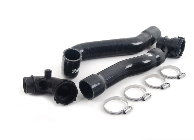
The ECS Tuning Silicone Radiator Hose Kit offers the following features:
• 3-ply black silicone upper and lower radiator hoses
• Brand new OE style hose connectors
• Brand new 304 stainless steel hose clamps
• Longer service life compared to OE hoses
• Higher resistance to breaking down and softening
• Peace of mind knowing that these common coolant leak sources have been replaced
Replacing the radiator hoses on your BMW E46 M3 is a rewarding project that an experienced technician will be able to complete in a few hours, plan accordingly based on your experience level. Before you begin, read and familiarize yourself with these instructions and make sure you have all the required tools on hand. Thank you for purchasing our BMW E46 M3 ECS Tuning Silicone Radiator Hose Kit, we appreciate your business!

Replacement Parts and Hardware:
• Coolant Temperature Sensor O-Ring
We would STRONGLY RECOMMEND that you replace the o-ring on the coolant temperature sensor, it is a very inexpensive part which is widely recognized as a common leak source. If you do choose to replace this o-ring, please be sure to obtain one BEFORE beginning the installation of this radiator hose kit to prevent any delays in completing the job and getting your vehicle back on the road.
Kit Contents:

Required Tools:
Note: The tools required for each step will be listed by the step number throughout these instructions.
Below is a list of the tools we used to install the BMW E46 M3 ECS Tuning Silicone Radiator Hose Kit. Additional tools may be required for any issues that arise during installation such as rust, corrosion, or broken and stripped fasteners. Tools with a part number listed are available on our website – click on their ES# link to view them.
• 1/4” Drive Ratchet
• 1/4” Extensions
• 3/8” Drive Ratchet
• 3/8” Drive Sockets: 6mm, 10mm
• 3/8” Drive Extensions
• Torx Bit Socket: T25
• Flat Blade Screwdriver
• Trim Removal Tool
• Hose Pick Tool Set
• Fan Clutch Tool Kit
• Coolant Evacuation Tool Kit
Shop Supplies and Materials
• Hand Cleaner/Degreaser
• Aerosol Brake Cleaner
• Shop Rags
• Aerosol Spray Lubricant/Penetrating Oil
Installation Notes:
- RH refers to the passenger side of the vehicle.
- LH refers to the driver side of the vehicle.
- Always use the proper torque specifications.
- If applicable to this installation, torque specifications will be listed throughout the document and at the end as well.
- Please read all of these instructions and familiarize yourself with the complete process BEFORE you begin.
General Preparation and Safety Information:
ECS Tuning cares about your health and safety. Please read the following safety information. This information pertains to automotive service in general, and while it may not pertain to every job you do, please remember and share these important safety tips.
- Park your car in a safe, well lit, level area.
- Shut the engine off and remove the key from the ignition switch.
- Make sure any remote start devices are properly disabled.
- ALWAYS wear safety glasses.
- Make sure the parking brake is applied until the vehicle is safely lifted and supported.
- If using an automotive lift, be sure and utilize the factory specified lift points. Lifting a vehicle in an incorrect location can cause damage to the suspension/running gear.
- When lifting a vehicle using a jack, always utilize the factory specified lift points. Lifting a vehicle in an incorrect location can cause damage to the suspension/running gear. ALWAYS support the vehicle with jack stands.
- ALWAYS read and follow all safety information and warnings for the equipment you are using.
Removing the Original Hoses
Step 1:
T25 Socket and Ratchet
Lift and safely support the vehicle. Working below the vehicle, loosen and remove the seven (7) screws which secure belly pan, then remove the belly pan and set it aside.

Step 2:
Working above the vehicle, remove the cap from the coolant reservoir and set it aside.
Caution: This step should only be performed AFTER the engine has been allowed to cool to reduce the risk of burns to the skin.

Step 3:
Locate the four push rivets which secure the air intake duct, then proceed to step 4.

Step 4:
Flat Blade Screwdriver
Remove the four push rivets which secure the air intake duct by lifting the core upwards as shown in the RH photo. Remove the duct from the vehicle and set it aside.

Step 5:
Lift the intake connection tube upwards to release it from the air box, then set the tube aside.

Step 6:
Pop off the two spring clips which secure the air box lid to the air box.

Step 7:
Flat Blade Screwdriver
Loosen the hose clamp which secures the air intake boot to the air box lid, then squeeze the two release tabs together on the MAF sensor electrical connector, and pull the connector off of the sensor.

Step 8:
Remove the air box lid and the air filter from the air box.

Step 9:
Locate the xenon control unit located on the LH side of the air box. Begin by pulling one of the rubber connector protectors out of the cover (left photo), then squeeze the release tab on the electrical connector, and pull the connector out of the control unit (bottom photo).

Step 10:
Begin by pulling the other rubber connector protector out of the cover (left photo), then squeeze the release tab on the electrical connector, and pull the connector out of the control unit (bottom photo).

Step 11:
Gently lift up on the xenon control unit cover to release it from the control unit, then remove the cover and set it aside.

Step 12:
10mm Socket and Ratchet
Remove the three nuts which secure the xenon control unit and the air box. Flip the xenon control unit out of the way, then lift the air box upwards to remove it from the vehicle.

Step 13:
Locate the air quality sensor on the RH side of the radiator, gently lift up to release it, then set it aside without disconnecting the electrical connector.

Step 14:
Flat Blade Screwdriver/Trim Removal Tool
Remove the two push rivets which secure the RH fan shroud trim by gently prying the core out of the rivet. Lift the fan shroud upwards to remove it from the vehicle and set it aside.

Step 15:
Flat Blade Screwdriver/Pick Tool
Gently pry the release tab on the auxiliary fan electrical connector to the side as shown in the photo, then pull the connector upwards out of the fan shroud.

Step 16:
Squeeze the two release tabs together on the auxiliary fan electrical connector and pull the connector apart.

Step 17:
Locate the coolant temperature sensor which is mounted on the lower radiator hose near the radiator. Squeeze the release tab inward and pull the connector off of the sensor.

Step 18:
Flat Blade Screwdriver/Angled Pick Tool
Locate the clip which secures the lower radiator hose connector to the radiator. Lift the clip upwards until it stops.

Step 19:
Place a large drain pan underneath the lower radiator hose to catch
the coolant as it drains. The lower radiator hose connector can now
be removed from the radiator, this can be achieved by gently rocking/ twisting the radiator hose up and down, and side to side while pulling it off of the radiator with firm, even force. Allow the coolant to drain from the system before continuing to the next step.
CAUTION: This step should only be performed AFTER the engine has been allowed to cool to reduce the risk of burns to the skin.

Step 20:
Flat Blade Screwdriver/Angled Pick Tool
Locate the clips which secure the coolant overflow pipe to the upper radiator hose (LH photo) and the upper radiator hose to the radiator (RH photo). Lift both clips upwards until they stop, then remove the upper radiator hose from the radiator and the coolant overflow pipe in the same manner as we removed the lower radiator hose.

Step 21:
Flat Blade Screwdriver/Trim Removal Tool
Remove the push rivet which secures the LH fan shroud trim by gently prying the core out of the rivet. Pull the fan shroud trim upwards approximately one inch, then pull it towards the LH side of the vehicle to pass the upper radiator hose through it, and finally remove the trim from the vehicle.

Step 22:
6mm Socket and Ratchet
Loosen the hose clamp on the upper radiator hose.

Step 23:
Remove the upper radiator hose by twisting the hose and pulling it as shown in the photo.
TECH TIP: A hose pick tool can be used to assist in loosening the seal between the hose and the engine.

Step 24:
Locate and identify the fan clutch assembly on the front of the engine. The fan clutch is removed by first HOLDING the water pump pulley stationary by placing the water pump locking tool over two of the water pump pulley bolts, then LOOSENING the fan clutch nut with the 32mm low profile wrench.
CAUTION: It is extremely important that you are aware of the fact that the fan clutch is REVERSE THREADED, meaning to loosen it you must turn it CLOCKWISE.

Step 25:
Fan Clutch Tool Kit
This illustration shows our Schwaben Fan Clutch Tool Kit in action as seen from ABOVE. We can clearly see the fan clutch tool kit and how the tools fit in place. You can see that the water pump locking tool is engaged
on TWO of the water pump bolts, and the 32mm side of the wrench is engaged on the fan clutch nut. Please continue to step 26 for another illustration of how the tool kit operates.

Step 26:
Fan Clutch Tool Kit
This illustration represents what you would see if you were looking THROUGH the radiator at the front of the engine. Please familiarize yourself with the steps in the illustration, then continue to step 27.
CAUTION: It is extremely important that you are aware of the fact that the fan clutch is REVERSE THREADED, meaning to loosen it you must turn it CLOCKWISE.

Step 27:
Fan Clutch Tool Kit
Loosen the fan clutch in the manner we have shown in the last two steps, but DO NOT attempt to remove it or fully loosen at this time. Simply loosen the fan clutch enough that you can turn it by hand, then continue to step 28.
Caution: It is extremely important that you are aware of the fact that the fan clutch is REVERSE THREADED, meaning to loosen it you must turn it CLOCKWISE.

Step 28:
T25 Socket and Ratchet
There are four screws which secure the radiator shroud to the radiator, and they can be difficult to see. Please reference the illustration to the right for their locations, please note that screw #1 must be accessed from the LH side of the radiator, while #2, 3, & 4 must be accessed from the back side. Loosen and remove these screws, then continue to step 29.

Step 29:
Once the screws have been removed from the radiator shroud, carefully unthread the fan clutch completely, being careful that it does not hit the radiator. Lift the radiator shroud and the fan clutch upwards out of the engine compartment together as shown in the photo.

Step 30:
6mm Socket and Ratchet
Loosen the hose clamp on the lower radiator hose, then remove the hose by twisting and pulling it just as we did with the upper radiator hose.
Tech Tip: A hose pick tool can be used to assist in loosening the seal between the hose and the engine.

Installing the New Silicone Hoses
Step 1:
Let’s take a moment and identify the components in the ECS Tuning Silicone Radiator Hose Kit.

Step 2:
Working on the original lower radiator hose connector, squeeze the two release tabs together on the coolant temperature sensor, then pull the sensor out of the hose connector.

Step 3:
Small pick or screwdriver
The o-ring on the coolant temperature sensor is a common source of leaks, so it is a good idea to replace it now while it is out of the vehicle.
To remove, simply pry the o-ring out of groove in the sensor and replace it with a new o-ring.

Step 4:
Lubricate the new o-ring with a small amount of clean coolant, then insert the sensor into the new lower radiator hose connector and push down until it clicks into place.
Note: The coolant temperature sensor only fits into the hose connector one way, if the sensor doesn’t slide in with ease, try rotating it until it fits easily.

Step 5:
Lubricate the o-rings in both hose connectors with a small amount of clean coolant.

Step 6:
Insert the lower radiator hose connector into the lower radiator hose, then orient the clamps as shown in the photo, but do not tighten the clamps at this time.
NOTE:
The ECS Tuning silicone radiator hoses will have the hose clamps pre-installed before shipping, it will be necessary to loosen the clamps in order to install the hoses onto the vehicle.

Step 7:
Install the lower radiator hose onto the radiator by pushing the connector onto the radiator as shown in the photo. Once the radiator hose connector is fully seated, push the clip down to lock it into place. Please note the orientation of the hose clamp in the photo.

Step 8:
Install the lower radiator hose to the engine by twisting and pushing until the hose is fully seated in place. Please note the orientation of the hose clamp in the photo.

Step 9:
6mm Socket and Ratchet
Once the lower radiator hose has been installed on both ends, tighten the clamp on the radiator hose connector as shown in the photo, then reconnect the coolant temperature sensor connector.

Step 10:
6mm Socket and Ratchet/Flat Blade Screwdriver
Tighten the clamp on the upper portion of the lower radiator hose as shown in the photo.

Step 11:
Carefully lower the radiator shroud and the fan clutch into the engine compartment together as shown in the photo, being careful to not hit the radiator on the way in. Partially thread the fan clutch onto the water pump but do not tighten it at this time.

Step 12:
T25 Socket and Ratchet
There are four mounting tabs on the radiator shroud which must ALL be lined up to matching notches/grooves in the radiator. Please reference the diagram on the right for the locations of these tabs on the shroud. Once all four tabs have been aligned and the shroud it fully seated, install and tighten the four shroud mounting screws until they are snug.

Step 13:
Reinstall the LH fan shroud trim into place, ensuring the mounting tab lines up with its respective groove in the fan shroud (see inserted photo). Secure the shroud trim into place with the push rivet.

Step 14:
NOTE: The ECS Tuning silicone radiator hoses will have the hose clamps pre-installed before shipping, it will be necessary to loosen the clamps in order to install the hoses onto the vehicle.

Step 15:
Remove the hose clamp from the radiator side of the upper radiator hose, but leave the hose clamp on the engine side of the hose. Install the hose onto the engine by twisting and pushing until it is fully seated in place.

Step 16:
Install the hose clamp onto the upper radiator hose, orienting it as shown in the photo, then insert the upper radiator hose connector into the upper radiator hose, but do not tighten the clamp at this time.

Step 17:
6mm Socket and Ratchet
Install the coolant overflow pipe into the upper radiator hose connector and lock it into place with the clip. Install the upper radiator hose connector onto the radiator and lock it into place with the clip. Once the upper radiator hose has been installed on both ends, tighten the clamps making sure they are oriented as shown in the photo.
• Reinstall the belly pan
• Reconnect the auxiliary fan and air quality sensor connectors
• Reinstall the air box and xenon control unit
• Reinstall the air box lid, air filter, MAF sensor and air intake boot

Step 18:
Flat Blade Screwdriver
With the engine OFF, loosen the bleeder screw approximately 1/2 turn, then pour a fresh mix of 50/50 antifreeze and water into the coolant reservoir, allowing the air bubbles to escape out of the bleeder. Close the bleeder screw once the stream of coolant shows no bubbles, then top
off the coolant reservoir to the appropriate level. Reinstall the coolant reservoir cap, then start the engine and allow it to warm up to operating temperature, and inspect the system for any coolant leaks.
TECH TIP: An alternative method to fill your cooling system without any air bubbles would be to use our Schwaben Coolant Evacuation Tool Kit with the “cone shape” adapter.

Step 19:
Reinstall the intake connection tube into the air box.

Step 20:
Reinstall the air intake duct onto the vehicle, then secure it into place with the push rivets.

Your E46 M3 ECS Tuning Silicone Radiator Hose Kit installation is now complete!
Interested in purchasing? Click HERE to shop now!