Introduction:
Our ECS Tuning Performance Baffled Oil Catch Cans and Brackets offer the following features:
• Constructed of strong and lightweight 6061-T6 billet aluminum
• Black anodized for corrosion resistance
• In-house designed by ECS Tuning Engineers
• Catch cans available with either an 8 ounce or 6-ounce reservoir
• Bracket kit Includes three different mounting plates for multiple installation configurations
• Catch cans are complete with a dipstick to check the content level and are fully serviceable
• Catch can flow is reversible for complete adaptability to any application

Todays direct fuel injection systems have taken engine performance to a whole new level, but there is a drawback as well. With no fuel vapors to clean the intake valves as they flow by, the oil particles that are drawn into the intake from the PCV system will deposit themselves onto the valves and intake ports. Over time this will result in an excessive carbon buildup, resulting in lost power and poor driveability. ECS Tuning now has the solution. We offer two different sized catch cans and a mounting bracket kit to allow you to custom build and install a catch can system on your car. Installing an ECS Tuning catch can in your PCV system separate the oil particles, contaminants, and moisture from the crankcase vapors, helping to keep your intake valves and ports clean, providing uninterrupted power and performance. Thank you for looking to ECS Tuning for all your performance and repair needs. We appreciate your business!
Catch Can Components:

PCV System Operation:
In order to properly install a catch can on any application, you must first have a basic understanding of the PCV system operation on your car so you can determine the correct position of the feed and return lines. We will begin here with a quick run-down of the PCV system.
PCV, or Positive Crankcase Ventilation, is an emission control which has been mandated for use since the 1960’s.
How it works:
No piston ring seals perfectly. Some combustion gas blows past the rings into the crankcase on each power stroke. The gas contains exhaust fumes, raw fuel, and water. These blow-by gasses will accumulate and build pressure inside the crankcase. If the pressure gets too great, it will push engine oil past seals and gaskets causing multiple oil leaks. The fuel and water also contaminate the engine oil.
Pre-PCV cars vented crankcase pressure to the atmosphere through a vent pipe or mesh restriction, commonly located in the oil fill cap. This was not only polluting the atmosphere but was inefficient and left a lot of raw blow-by gas and water inside the crankcase, where it quickly contaminated the engine oil, creating sludge and oil breakdown.
The modern PCV system draws these harmful blow-by gasses and vapors back to the intake plenum where they make up a small part of the combustion air charge. More importantly, the system replaces blow-by contamination with fresh, filtered air that dilutes contamination to reduce concentrations of acids, oxidants, and water in the engine oil.
To minimize the amount of liquid oil drawn through the PCV valve, many modern engine designs – including those from Euro car manufacturers, now include a separator that removes liquid oil from recirculated gases and returns it to the crankcase before it can be sucked back into the intake. This reduces oil consumption and protects sensors and catalytic converters from contamination, however in many cases they are not completely successful at removing all of the oil.
Turbocharged engines pose special problems since boost pressure increases blow-by volume and can easily turn manifold vacuum into boost pressure greater than crankcase pressure, disrupting normal PCV flow. Special crankcase ventilation methods are required in boosted engines, such as more sophisticated oil separation devices and/or catch cans.
Catch Can Installation Guidelines:
When installing your catch can, first identify the components of your PCV system and determine where you will locate the feed and return lines.
Next, determine where you will mount the catch can.
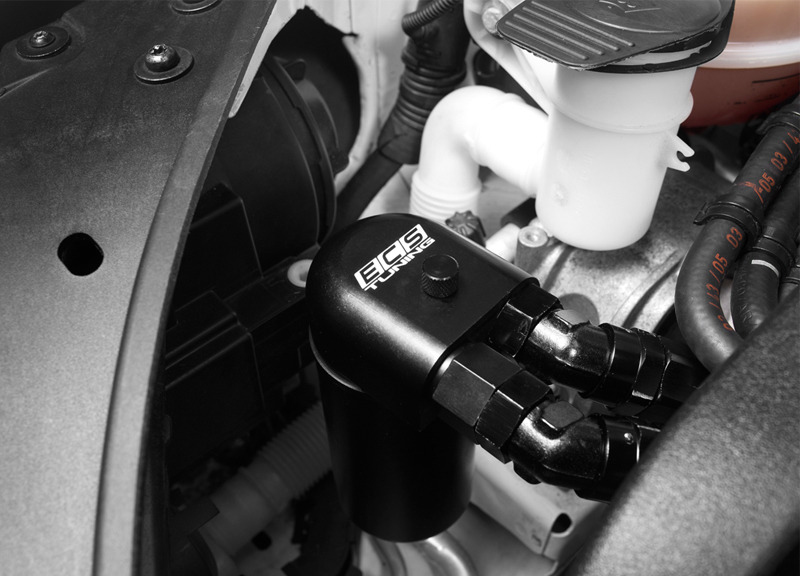
All of our catch cans are assembled with the feed (inlet) on the left and the return (outlet) on the right. To improve your options for line routing and catch can location, you may reverse the flow of the catch can.
Obtain the necessary hardware and lines you will need. The fittings on our catch can separators are -10 AN ORB (O-ring boss) fittings.
We recommend the use of braided hose that is oil and fuel resistant and rated for automotive use.
Our bracket kit gives you a number of different options for mounting the catch can, some examples are shown on the right.
Route your feed and return lines so they do not interfere with or rub on any moving or hot components.
Connect the feed line between the crankcase and the catch can. Connect the return line between the catch can and your intake system.

Our catch cans are designed so the separator will be installed through the top of the bracket, then the reservoir threaded on from the bottom. When the reservoir is completely tightened, it will lock the catch can in place in the bracket.
When installing the separator into the bracket, be sure and ALWAYS remove the o-ring seal first. If you do not remove it, it will be damaged.
After the separator is through the bracket, reinstall the o-ring seal.
Lubricate the o-ring seal with clean engine oil before threading on the reservoir.
It is only necessary to tighten the reservoir by hand. Do not use any tools.

Cleaning and Maintenance:
Step 1:
We recommend that you check the level of the waste in your catch can on a regular basis. Start with once a week until you determine the amount of time it takes your car to fill the reservoir.
Note that if you have the 8-ounce reservoir, the dipstick will not reach all the way to the bottom. When you begin to see waste register on the dipstick, you already have about an inch of buildup in the bottom.
The dipstick reaches the bottom of the 6-ounce reservoir. Waste will register on the dipstick as soon as it begins to collect.
Empty and clean either reservoir when the waste registers approximately 2” up on the dipstick.

Step 2:
About twice a year, we recommend that you remove the separator for cleaning. To remove it, remove the lines and the reservoir. Remember to remove the o-ring seal, then lift the separator out of the bracket.
NOTE: If the o-ring seal needs to be replaced, it is available as a replacement part on our website, ES#2960397.

Step 3:
Once you have removed the separator, note the position of the baffle inside. The feed side of the separator has a number of small holes in it. Through the return side you will only be able to see a flat plate.
NOTE: The baffle can be reversed for custom applications and it is important to note the position now so the separator is reassembled in the correct order. If your catch can is set up for reverse ow, these pictures will appear “backwards”, but the procedure will be the same.

Step 4:
Using the 2.5mm allen wrench included with the kit, remove the two baffle plate screws.

Step 5:
Lift the baffle plate out of the separator housing.

Step 6:
Lift the remaining baffles out of the separator housing.

Step 7:
Note the positions of the fixed baffle and the reversing baffle.

Step 8:
Slide the two baffles apart.

Step 9:
Clean the separator baffles, housing, and reservoir, using any mild cleanser or solvent. Note in the picture on the right that the fixed baffle is shorter than the reversing baffle.
NOTE: Any mild cleanser or solvent can be used to clean the catch can, however, we recommend that you test all cleansers on an inconspicuous area inside the reservoir to check for discoloration before you clean the outside surfaces.

Step 10:
Reassemble the baffles into the separator housing and make sure that the baffles have not been reversed and the feed and return sides are positioned correctly. Reference step 4 to make sure that you have installed the baffle plate correctly.
Reinstall the catch can into your car. Be sure and lubricate all o-rings with clean engine oil.

Cold Temperature Warning:
In cold temperatures, the crank vent system will generate a much greater amount of moisture which can present a risk of freezing.
When the temperature outside approaches freezing, your catch can should be cleaned on a weekly basis to prevent freeze up of the crank vent system and damage to engine seals.
When the temperature reaches freezing and below, we recommend disconnecting the feed and return lines and installing the original PCV hose between the intake pipe and PCV valve assembly.
Reversing the flow of the catch can:
Step 1:
You can reverse the flow of your catch can in order to create the best mounting location and line routing for your application. To begin, look into the separator and identify the feed and return side as the catch
can have been originally assembled. The feed side of the separator has a number of small holes in it. Through the return side, you will only be able to see a flat plate.
Step 2:
Using the 2.5mm allen wrench included with the separator, remove the two baffle plate screws.

Step 3:
Lift the baffle plate out of the separator housing.

Step 4:
Lift the remaining baffles out of the separator housing. Note the position of the inlet screen on the reversing baffle (arrow).

Step 5:
Again note the positions of the fixed baffle and the reversing baffle.

Step 6:
Slide the two baffles apart.

Step 7:
Flip the reversing baffle and slide it back onto the fixed baffle.

Step 8:
Inspect the inside of the separator housing. You will see that there are two sets of threaded holes for the baffle plate screws. When you reverse the flow, you will use the opposite holes when reinstalling the baffle plate screws.

Step 9:
Reinstall the baffles into the separator housing. Note that the inlet screen on the reversing baffle should now be located on the opposite side.

Step 10:
Flip the baffle plate so it is opposite of the removal position and place it back into the separator housing.

Step 11:
Reinstall the baffle plate screws utilizing the opposite holes in the separator housing. Compare the new baffle plate position with step 2 to make sure it is properly installed for reverse flow.

Step 12:
Your reverse flow separator will now have the feed side and return side located as shown in the photo.

Your Catch Can Installation is complete!
Interested in purchasing?
ECS Performance Baffled Oil Catch Cans
Capture harmful oil vapors and keep your intake tract clean.