Introduction:
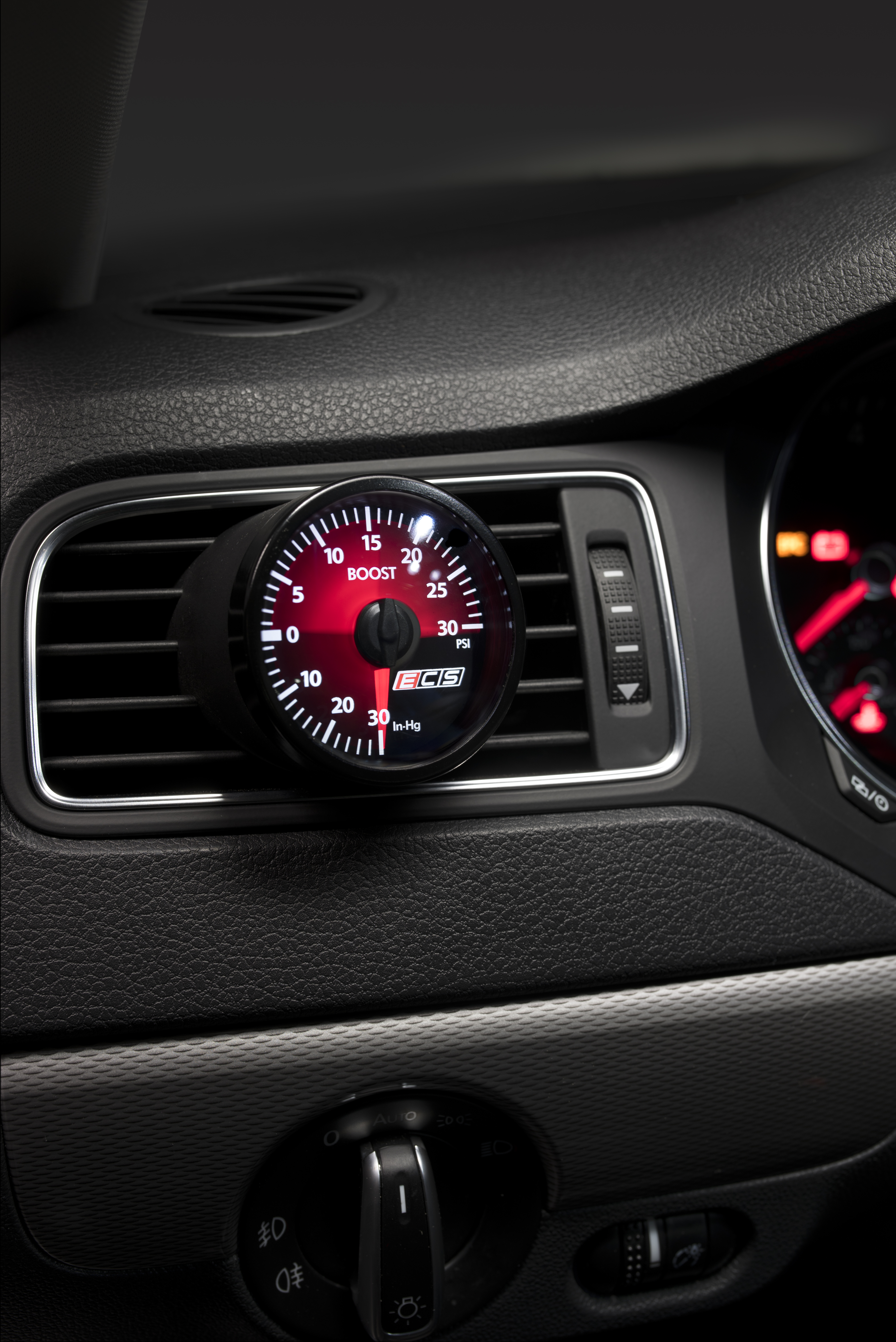
Looking to add style and function to your dash? Look no further, ECS Tuning has designed a vent pod which will seamlessly integrate into the dash of your MK6 Jetta for a factory appearance. Our vent pod is compatible with most 52mm (2 1/16″) boost gauges, and it angles the gauge towards the driver so you can monitor your boost levels without taking your eyes off the road!
Part Numbers: ES3183947, ES3247336


Installation:
Section 1: Installing the Boost Tap/Routing the Vacuum Line
Step 1:
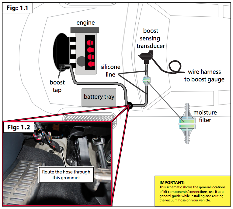
The illustration below shows kit component general locations and connections. Engine vacuum/boost is sampled from a boost tap on the engine (not included with all kits). The small silicone vacuum line connected to the boost tap is then routed through the engine compartment to a grommet in the firewall, where it enters the cabin. (Fig: 1.1)
Step 2:
• Inside the cabin, pierce a hole in the grommet near the foot rest (Fig: 1.2), then pull the hose through.
• Install the moisture filter between the vacuum source and the transducer. (Fig: 1.1)
• The transducer wiring harness will be routed to the gauge later.
Step 3:
Route and secure all hoses, harnesses, and the transducer itself in order to avoid interference with moving parts such as the steering shaft and pedals.
Section 2: Installing the Vent Pod and Gauge
Step 1:
• Pry on the front edge of the left dashboard side panel with a non-marring trim removal tool. (Fig: 2.1)
• Pop the panel from its snap-clip fasteners and lay it aside.
Step 2:
• Reach around and push from the rear to pop the left side vent out of the dash. (Fig: 2.2)
• The surrounding trim will come out with the vent, so work carefully to avoid stressing the plastic.
Step 3:
• Pry gently around the entire perimeter of the dashboard trim panel with a non-marring trim removal tool, releasing all of the plastic snap retainers as you go along (highlighted with arrows in Fig: 2.3).
• The dashboard trim panel can be easily broken, so work slowly and methodically while releasing it.

Step 4:
• When all clips are released, tip the front of the panel forward slightly, but don’t remove it. (Fig: 2.4)
• It is still connected to the top of the steering column with a fabric trim piece.
• A blanket or cloth can be placed on top of the steering column to protect the panel from scratches.
Step 5:
• Release the electrical connectors from behind the center vent assembly. (Fig: 2.5)
• Swing the wires aside so they are out of the way.
Step 6:
• Locate all of the tabs which secure the LH vent housing to the dashboard trim panel. (Fig: 2.6)
• Some of the tabs are not shown in the photo as they run around the entire perimeter of the vent.
NOTE: The next several steps were taken with the trim panel removed for clarity, but you can perform all of these steps with the panel flipped down as shown in Fig: 2.4.
Step 7:
• Carefully pry up on each of the tabs to release the LH vent housing from the trim panel. (Fig: 2.7)
• The tabs can be easily broken, so work slowly and methodically while releasing them.

Step 8:
When all tabs have been released, pull the LH vent housing off of the trim panel. (Fig: 2.8)
Step 9:
• Locate the retaining tabs on the open/close wheel trim cover (Fig: 2.9).
• Carefully pry each of the tabs to release and remove the trim cover from the vent housing
Step 10:
Use a suitable non-marring tool to pry gently on the side retaining tabs which hold the outer louvers into the vent housing. (Fig: 2.10)
• Pry the outer louvers away from the housing slightly; move it out just far enough to clear the retainers.
Step 11:
• Moving to the opposite end of the vent housing, pry between the edge of the outer louver side rail and housing with a suitable non-marring tool. (Fig: 2.11)
• When all tabs are released, remove the outer louvers from the housing (inset photo in Fig: 2.11)

Step 12:
• Locate the retaining tabs which secure the inner louvers into the vent housing. (Fig: 2.12)
• Release all four tabs one by one with a small screwdriver or pick.
Step 13:
• Pull the inner louvers out of the housing. (Fig: 2.13)
Step 14:
• Gently pry between the outer louvers and the side rails at the points shown (arrows in Fig: 2.14).
• Completely remove the side rail from the louvers.
Step 15:
• Repeat Step 14 to release the other side rail from the outer louvers. (Fig: 2.15)
• Set the side rails aside, we will be reusing them on the new angled vent pod.

Step 16:
• Install the side rails onto the new angled vent pod. (Fig: 2.16) NOTE: You may need to manipulate the louvers in the vent pod slightly in order to align them with the side rails.
Step 17:
• Drill a 1/2” hole in the bottom of the vent housing (arrow in Fig: 2.17).
• The hole location can vary slightly as long as the wires do not interfere with the vent open/close flap, the vent open/close linkage, or the installed vent pod.
Step 18:
• Release the headlight switch from the dashboard using the following procedure (Fig: 2.18):
1. Make sure the headlight switch is in the “off” position.
2. Firmly push in on the center of the switch knob until it depresses inward.
3. Turn the switch slightly to the right until it stops (between “off” and “park”)
NOTE: The switch knob will stay in this position as shown in the picture.
Step 19:
• Pull the headlight switch out of the dash. (Fig: 2.19)
• It is not necessary to disconnect the wiring harness from the back of the switch.
Step 20:
• Route the transducer cable from the underdash area, up behind the dashboard and out through the LH vent opening. (Fig: 2.20)
• Route the power harness down through the LH vent opening and out the hole for the headlight switch. (Fig: 2.20)
• Pull the cables through far enough to reach the area where the gauge will be installed in the vent pod.
• Secure the transducer and vacuum line underneath the dash with the supplied zip ties, keeping them away from any moving components.

Step 21:
• One at a time, insert the power and boost sensor harnesses through the bottom of the vent housing and pull them out the front as shown (Fig: 2.21).
• Rest the vent housing in the opening of the dash, but do not install it into place. It will remain here for the next few steps.
Step 22:
• Install and tighten the two nuts to hold the gauge into the vent pod. (Fig: 2.22)
• These nuts only need to be tightened by hand turning the socket or carefully using a 1/4” driver.
• Using a ratchet or excessive force will risk breaking the studs on the gauge.
• Insert the power harness (4-pin) connector into the RH plug on the back of the gauge.
• Insert the transducer harness (3-pin) connector into the center plug on the back of the gauge.
Step 23:
• Reassemble the LH vent in the reverse order. (Fig: 2.23)
Step 24:
• Reinstall the LH vent into the dashboard trim panel. (Fig: 2.24)
• Ensure that all of the retaining tabs are properly aligned and fully seated while installing the vent into the panel.

Section 3: Electrical Connections
Step 1:
• Crimp one of the spade connectors onto the pre-stripped end of each of the four wires in the gauge power harness: red, black, white, and green. (Fig: 3.1)
• You may choose to install heat-shrink tubing over the end of the spade terminals and wire for a clean appearance.
Step 2:
• You will be installing four T-taps onto the headlight wiring harness.
• Inspect Fig: 3.2, then follow the procedure outlined in steps 3 & 4.
Step 3:
• Position the T-tap so the wire is located in the groove of the blade. (Fig: 3.3)
Step 4:
• Fold the top of the T-tap over then squeeze it together wth curved jaw pliers until you hear a “click” indicating that the T-tap is fully closed. (Fig: 3.4)
• Repeat this process on the remaining three wires in the gauge power harness. (reference Fig: 3.2)

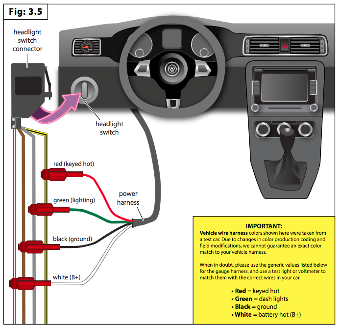
Step 5:
• Connect the four spade connectors to the T-taps using the illustration below for reference. (Fig: 3.5). • Firmly support each T-tap from behind as you push the spade connector into place.
• These are a tight fit so you will have to push fairly hard to fully seat the spade connectors.
Section 4: Reassembly
Step 1:
• Guide the headlight switch back into the dash. (Fig: 4.1)
• Make sure that the wires fall freely back into the dash and do not get caught on anything.
• Push on the switch until you hear a click indicating that it is fully seated into the dash.
Step 2:
• Reinstall the electrical connectors behind the center vent assembly.
• Reinstall the dashboard trim panel. (Fig: 4.2)
• Reinstall the left dashboard side panel
Step 3:
• Turn the ignition on and ensure that the needle sweeps across the entire gauge, then rests at “zero”. (Fig: 4.3)
• Start the engine and check the gauge operation and lighting.