
The B7 A4 has plenty of potential to graduate from its luxury commuter status to that of a more performance oriented daily driver. It does have a few drawbacks we have covered in a previous article about the common problems B7 A4 owners can expect, but today’s DIY helps tackle some of those while also providing a noticeable improvement to horsepower and a visual upgrade to the engine bay. Our in-house designed Kohlefaser Luft-Technik Intake System offers decreased intake air temperatures, a moderate increase in power by itself, and gives you the room to grow by pairing with other basic performance upgrades like a downpipe or software upgrade. Let’s dig in to this easy install and bring your B7 A4 up a notch.
Step 1:

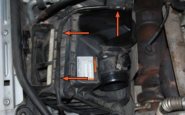
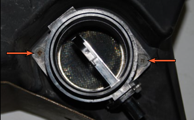
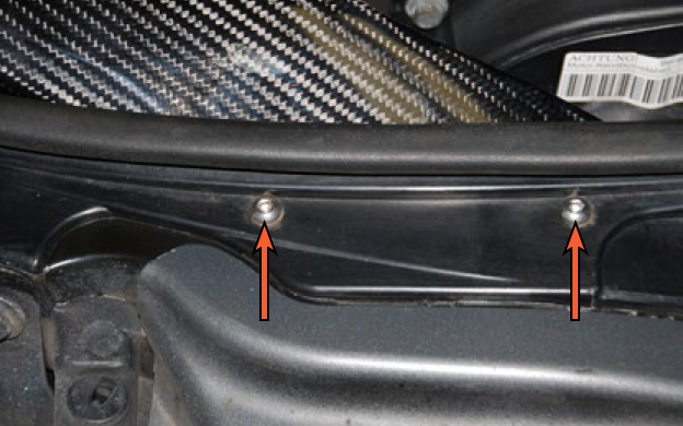
Locate the two air scoop mounting screws and remove them. Depending on the production date will you find that you may have either torx or Phillips head fasteners.
Step 2:
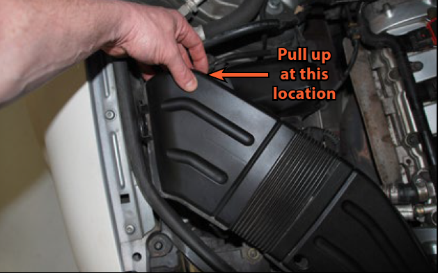
Pull up on the intake duct at the location shown to separate it from the airbox. Then pull it rearward to pull the air scoop out of the front core support and remove it from the car.
Step 3:
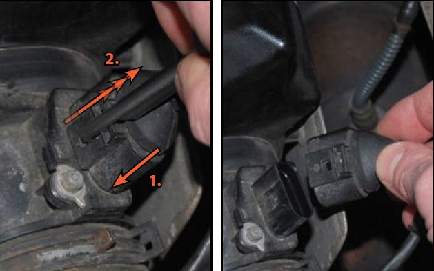
Disconnect the Mass Air Flow Sensor. We are using our Schwaben Connector Release Tool to make this easier. The trick to releasing these “push and pull” style of connectors is to first push the connector down, which will release the tension between the locking tab and the catch on the sensor, then insert the release tool and pull up. This will raise the locking tab in the connector just far enough to clear the catch on the sensor and it will slide off with incredible ease.
Step 4:
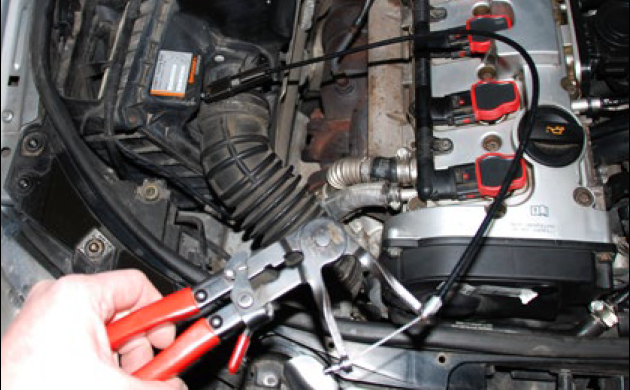
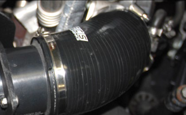
Loosen the spring clamps where the original turbo inlet tube attaches to the Mass Air Flow sensor and the turbo inlet. Pull the hose off both ends and remove it.
NOTE: There is a large lip on the inlet of the turbo and you will have to pull hard on the base of the turbo inlet tube in order to remove it.
TECH TIP: If you don’t have locking hose clamp pliers, channel lock pliers can be used, but BE CAREFUL! The clamps can easily spring off and cause personal injury or damage to the vehicle. Wear Safety Glasses!
Step 5:
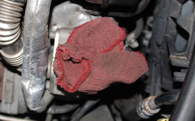
Place a clean rag into the turbocharger inlet to prevent anything from falling into it.
Step 6:
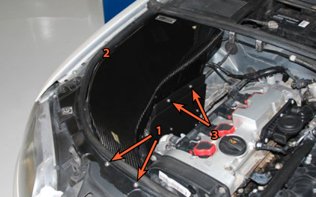
Pull the wiring harness off the airbox at the three locations indicated in the picture and position it to the side.
Step 7:

Remove the center pin from the air box mounting rivet by sliding it out.
Step 8:
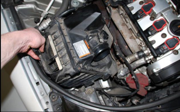
Pull up on the air box assembly to pull the lower mounting grommets out of the frame rails and remove it from the car.
NOTE: You may need to grab the air box near the base and pull firmly upwards in order to unseat the lower mounting grommets.
Step 9:

Reinstall the center pin for the original airbox mounting rivet.
NOTE: This is a mounting point for the Carbon Fiber Intake Lid. The center pin must be reinstalled to keep the rivet from coming out.
Step 10:

It is common for the airbox mounting grommets to stick in the subframe. Check underneath the airbox and remove the grommet(s) if they have stuck in their holes.
Installing the Luft-Tech Intake
Step 1:

Push the three heat shield “S” clips onto the auxiliary heat shield in the locations shown. Make sure they are fully seated and that the bottom half of each clip is located below the heat shield, as shown in the inset photo.
NOTE: Both sides of these clips are the same. There is no actual “top” or “bottom” of the clip until they are installed and we are able to then reference a physical location as “top” or “bottom”.
Step 2:
Push the auxiliary heat shield into place on the edge of the exhaust manifold shield as shown.
Step 3:
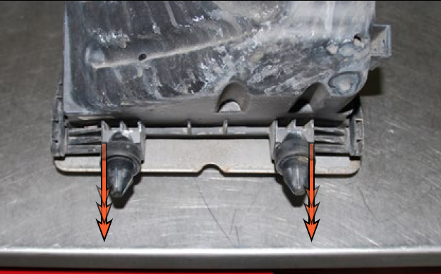
Pull both of the original mounting grommets off of the airbox or pull them out of the subframe if they stuck there during removal.
Step 4:

Push them onto the pre-installed grommet studs on the bottom of the new intake base plate.
Step 5:
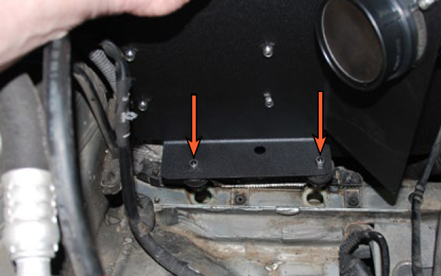
Remove the two mounting screws and pull the Mass Air Flow Sensor off of the original air box.
Step 6:

Insert one of the new M6 x 14 Mass Air Flow sensor mounting screws into one of the ears on the sensor flange, hold it in place with your finger, then place the new Mass Air Flow Sensor seal around the sensor flange and over the screw.
Step 7:

Install the Mass Air Flow Sensor into the new intake base plate. Inspect the picture on the right and install the sensor so the electrical connector is located on the opposite side as the original installation position. Make sure the seal is located between the sensor and the intake base plate. Install both screws and nuts loosely at first, then tighten them both. The nuts should be located on the inside of the intake base plate.
Step 8:
Install the intake base plate into the car by pushing it downward until the mounting grommets are fully seated in the subframe.
Step 9:
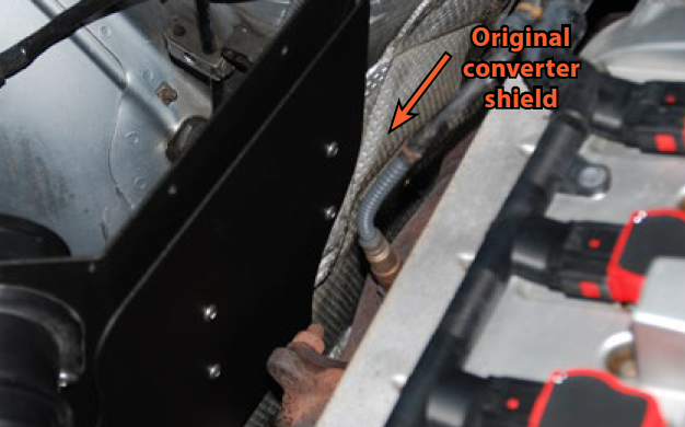
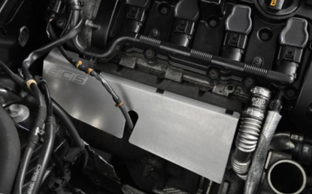
For a cleaner appearance, locate the original converter shield between the outer heat shield and inner heat shield/intake base plate.
Step 10:
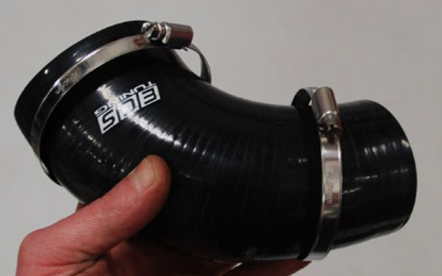
Place the turbo inlet hose clamps over the silicone turbo inlet hose, noting that the larger hose end and clamp will be located on the Mass Air Flow Sensor and the smaller end and clamp will be located on the turbo.
Step 11:
Remove the rag in the turbo inlet, then push the silicone turbo inlet tube over the Mass Air Flow Sensor and turbo Inlet. Make sure the tube is completely installed on both ends and tighten the clamps.
Step 12:

Push the air filter all the way onto the end of the Mass Air Flow Sensor and tighten the clamp, then plug the electrical connector back into the sensor.
Step 13:
Now it’s time to install the new carbon fiber intake lid.
CAUTION: Be sure to read steps 13 through 16 completely before attempting to install the intake lid.
The lid mounts in three locations:
1. Two screws secure it to the radiator core support.
2. The mounting tab on the RH side of the lid slips into the original air box mounting rivet on the RH inner fender.
3. Two screws secure it to the inner heat shield.
Step 14:

Begin by inserting the air scoop into the radiator core support (mounting location 1), then tilt it backwards and slip the mounting tab onto the airbox mounting rivet (location 2). Make sure the carbon fiber lid is positioned to the inside of the heat shield (location 3).
There are two things in particular that you will need to pay attention to:
1. The air scoop is a tight fit into the radiator core support. You may need to squeeze it together slightly to get it to slip into place.
2. Due to manufacturing tolerances, you may have to slightly enlarge the holes in the radiator core support.
Step 15:
If the air scoop mounting holes do not line up fore and aft, remove the intake lid and reinstall it, squeezing the air scoop together to allow it to slip into place.
If the air scoop mounting holes do not line up side to side, remove the intake lid and slightly enlarge the holes in the radiator core support using a drill bit.
Once you have confirmed that the holes line up, loosely install both air scoop mounting screws into the carbon fiber intake lid.
Step 16:

Align the holes in the intake lid with the holes in the heat shield. Loosely install the two lid to heat shield mounting screws with washers. Once you have installed all four mounting screws loosely and confirmed that everything lines up properly, hand tighten all four mounting screws.
Your Kohlefaser Luft-Technik installation is complete!
SHOP AUDI B7 A4 Kohlefaser Luft-Technik Intake
SHOP ALL AUDI B7 A4 COLD AIR INTAKES
RELATED ARTICLE: FIXING COMMON PROBLEMS WITH THE AUDI B7 A4 2.0T

RELATED ARTICLE: HOW TO ADD 100 HP TO YOUR AUDI B7 A4 2.0T