Introduction
The art of engineering – the defining trait of ECS Tuning – has been skillfully applied to yet another canvas, with our new Audi B9 A4 2.0T Kohlefaser Luft-Technik Intake System. A sleek, beautiful machine from the factory, the stock 2.0T performs well but yearns for more. Our Kohlefaser Luft-Technik Intake Systems have a track record of success, and our newest is no exception. Proven on the dyno and proven on the street, our new B9 A4 2.0T Kohlefaser Luft-Technik Intake opens up a new world of performance for the 2.0T and compliments the lines and under hood style with tasteful precision. The easy installation, accurate fit, and affordable price make every aspect of it a winner and prove once again that we are engineering works of art.

Take your time and enjoy the project, it’ll only take you a couple of hours or less. Read these instructions completely first, and with the project overview under your belt, you’ll breeze right through it. Just to make sure you have everything you need, reference the required tool list on Page 6 before you begin. Thank you for looking to ECS Tuning for all your performance and repair needs, we appreciate your business!
Kit Contents


Required Tools
• Protecta-Sockets (for lug nuts): ES#2221243
• 3⁄8” Drive Ratchet: ES#2765902
• 3⁄8” Drive Torque Wrench: ES#2221245
• 3⁄8” Drive Deep and Shallow Sockets: ES#2763772
• 3⁄8” Drive Extensions: ES#2804822
• Hydraulic Floor Jack: ES#240941
• Torx Drivers and Sockets: ES#11417/8
• 1⁄2” Drive Deep and Shallow Sockets: ES#2839106
• 1⁄2” Drive Ratchet
• 1⁄2” Drive Extensions
• 1⁄2” Drive Torque Wrench: ES#2221244
• 1⁄2” Drive Breaker Bar: ES#2776653
• Bench Mounted Vise
• Crows Foot Wrenches
• Hook and Pick Tool Set: ES#2778980
• 1⁄4” Drive Ratchet: ES#2823235
• 1⁄4” Drive Deep and Shallow Sockets: ES#2823235
• 1⁄4” Drive Extensions: ES#2823235
• Plier and Cutter Set: ES#2804496
• Flat and Phillips Screwdrivers: ES#2225921
• Jack Stands: ES#2763355
• Ball Pein Hammers
• Pry Bar Set: ES#1899378
• Electric/Cordless Drill
• Wire Strippers/Crimpers
• Razor Blade
• Punch and Chisel Set
• Hex Bit (Allen) Wrenches and Sockets: ES#11420
• Thread Repair Tools: ES#1306824
• Open/Boxed End Wrench Set: ES#2765907
Removing the Original Intake
Step 1:
Look along the back edge of the hood release lever and you will see a release button.

Step 2:
Push in on the button with your finger, then pull the release lever off.

Step 3:
Remove the radiator shroud by pulling up on the front edge to unclip it from the grille, then pull it forward to slide it out of the core support.

Step 4:
T25 Torx
Remove the two intake duct screws.

Step 5:
Pull the intake duct back from the core support, then pull it out of the air box.
Step 5:
Pull the intake duct back from the core support, then pull it out of the air box.

Step 6:
Remove the engine cover by pulling up at the four corners.

Step 7:
Small Flat Blade Screwdriver
Locate the vent tube (highlighted) that attaches to the turbo inlet pipe elbow, then carefully remove it from the elbow.

Step 8:
Flat Blade Screwdriver -or- 7mm Socket & Ratchet
Loosen the upper hose clamp on the turbo inlet pipe at the air box.

Step 9:
Loosen the lower hose clamp on the turbo inlet pipe at the turbo, then remove the pipe from the vehicle.

Step 10:
Now, simply pull straight up on the air box with both hands and remove it.

Step 11:
Place a rag over the turbo inlet to prevent anything from falling into it.

Step 12:
5mm Allen
Remove the two screws (arrows) from the original turbo heat shield and set them aside, you’ll be using them in just a few steps.

Removal is complete, you’re ready to install the new intake!
Installing the new intake
Step 1:
Carefully guide the ECS secondary heat shield into place as shown, using caution not to snag any wires or scratch the paint with the edges of the shield.

Step 2:
5mm Allen

Step 3:
Using four (4) M6 steel flat washers and two (2) M6 lock nuts, loosely install the two heat shield foot adapters into the elongated slots in the primary heat shield. Be sure to locate a washer on the top and bottom of the heat shield for each foot.

Step 4:
8mm, 10mm Wrenches
Hold each foot stationary with an 8mm wrench while you tighten the nut with a 10mm wrench until snug.
The placement of the feet inside these slots may vary from one vehicle to another. If you have trouble getting the intake components to line up, later on, you can use these slots to move the heat shield inward or outward depending on your needs.

Step 5:
Pull all three of the rubber mounts off the bottom of the original air box.

Step 6:
Push two of the rubber mounts onto the foot adapters of the primary heat shield.

Step 7:
Install the grommet into the ear of the primary heat shield.

Step 8:
Razor Blade
Cut the small edge seal (highlighted) to length as required, then install it onto the primary heat shield in the areas shown. Note the following:
1: Leave enough of a gap by these mounting holes to install the anodized air filter coupler.

Step 9:
Small Flat Blade Screwdriver
Gently pry the plastic cap out of the negative jump-start boss. Note the threads in the center of the boss, we will be utilizing them to mount the primary heat shield later on.

Step 10:
Install the primary heat shield into place by lining up the rubber mounts with the holes in the frame horn, guiding the fuel lines into the heat shield cut out, then pushing it down into place until the mounts are fully seated.

Step 11:
5mm Allen
Install and tighten the M8x16mm bolt through the grommet.

Step 12:
Align the anodized air filter coupler with the mounting holes in the primary heat shield as shown in the photo.

Step 13:
Place an M5 steel washer onto each of the M5 screws, then start both screws through the primary heat shield and into the anodized air filter coupler. If the air filter coupler is properly lined up with the primary heat shield, both screws should start easily and thread in smoothly.

Step 14:
3mm Allen
Tighten both of the M5 screws.

Step 15:
Place the hose clamps over the end of the silicone turbo inlet hose. Be sure and place the 70-90mm hose clamp over the larger end and the 60- 80mm hose clamp over the smaller end, and face the two clamp screws as shown in the photo.

Step 16:
Remove the rag that is covering the turbo inlet, then slide the turbo inlet hose onto the anodized air filter coupler and the turbo inlet. Do not tighten the clamps at this time.

Step 17:
Flat Blade Screwdriver – OR – 7mm Socket & Ratchet
Align the clamps on the top and bottom of the turbo inlet hose, then fully tighten them. As you can see here, we have rotated them so the clamp drive is underneath, providing a clean look.

Step 18:
Push the 90 degree elbow into the silicone turbo inlet hose and reconnect the vent tube.

Step 19:
Flat Blade Screwdriver – OR – 8mm Socket & Ratchet
Push the air filter onto the end of the coupler, then tighten the filter clamp. As seen here, push the filter on by the end, DO NOT hold it by the pleats. They will easily distort and bend, and take away from the clean look. Also, note that we rotated the clamp drive underneath before we tightened it.

Step 20:
Install the remaining length of small edge seal (highlighted) along the top edge of the primary heat shield as shown, then trim it just before it reaches the hole for the silicone turbo inlet hose.

Step 21:
Install the remaining rubber mount into the factory air box mounting location near the end of the air filter. We will be utilizing this mount for the corner of the carbon fiber air box lid.

Step 22:
4mm Allen, 10mm Wrench
Using the supplied M6x50mm screw, M6 flat steel washer, and M6 lock nut, secure the factory inlet shroud to the core support.
We are doing this to replace one of the intake duct screws we removed in Step 4 on Page 10, but be sure to use the mounting hole shown in the photo. The remaining mounting hole will be used to secure the carbon fiber air box lid later on.

Step 23:
Locate the inner mounting tab on the bottom side of the carbon fiber air box lid, this is the part of the lid which will utilize the factory air box rubber mount near the air filter.

Step 24:
10mm Wrench
Install the M6 ball stud into the carbon fiber air box lid using the hardware listed in the photo. Tighten the M6 lock nut until it is snug.
CAUTION: Be careful not to over tighten the hardware, over tightening can cause the carbon fiber to crack.

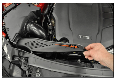
Step 25:
To install the carbon fiber air box lid, begin by inserting it into the air inlet shroud along the front of the engine compartment. Next we need to pivot the lid downward until it rests over the primary heat shield. In most cases, you’ll need to squeeze the silicone turbo inlet hose by hand while pivoting the lid in order to get it into position.

Step 26:
Ensure that the carbon fiber air box lid is installed OVER the primary heat shield. The photo on the right shows the edge of the lid, when installed properly the heat shield will be tucked up behind the lid along this edge.

Step 27:
Ensure that the ball stud on the carbon fiber air box lid lines up with the rubber mount, then push it into place.

Step 28:
4mm Allen
Place an M6 nylon washer onto the end of the M6x16mm screw, then thread the screw through the carbon fiber air box lid and into the primary heat shield and tighten it until it is snug.
CAUTION: Be careful not to over tighten the hardware, over tightening can cause the carbon ber to crack.

Step 29:
4mm Allen, 10mm Wrench
Using the supplied M6x60mm screw, M6 nylon washer, and M6 lock nut, secure the carbon fiber air box lid to the core support. Be sure to use the mounting hole shown in the photo.

Step 30:
Reinstall the radiator shroud, hood release lever and engine cover.

Reflect-A-Gold Installation
If you have purchased the optional Reflect-A-Gold heat deflection, apply the two pieces to the primary heat shield in the locations shown. Be sure to wipe the surface of the heat shield clean with a surface prep solvent or an alcohol wipe to remove any traces of oil or contaminants. Line them up, making sure to leave room at the rivets and hardware, remove the backing and carefully apply it, smoothing out any wrinkles along the way.

Interested in purchasing?
ECS Kohlefaser Luft-Technik Intake System
Engineered for dyno proven performance and show quality looks!