
Now you can pop your rear hatch with the press of a single button on your key fob. The innovative Hatch Pop Kit includes a solenoid-operated latch release, wire harness, spring loaded stop bumpers, two strong lifting struts, and all the mounting hardware you need.
Installation requires removal of the rear hatch inner trim panel. Inside the hatch, you will install mounting grommets, a new solenoid actuator, and a special patch harness designed for plug-and-play simplicity.
Tools required are simple, and include a non-marring plastic trim removal tool, Phillips and common head screwdrivers, and pliers.
Let’s jump right in!
Installation
Raise the rear hatch.
Remove the two Phillips head screws located inside the pull recesses in the rear trim panel (circled).
Use a trim removal tool to pry the inner panel away from the hatch.
The panel is held in place by metal spring clips (arrows) that should pop free one at a time as you pry around the perimeter in the panel.
After removing the two screws in the trim panel, pry down with a plastic trim removal tool.

Work around the perimeter of the panel until it comes loose. Remove it.
Note: The trim tool shown is from the 5-piece trim removal set, ES517779.
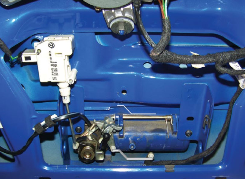
With the panel removed, the lock and latch mechanisms are exposed.
Original Hatch Components
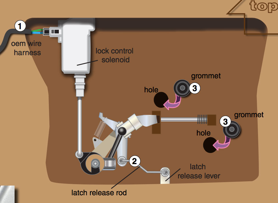
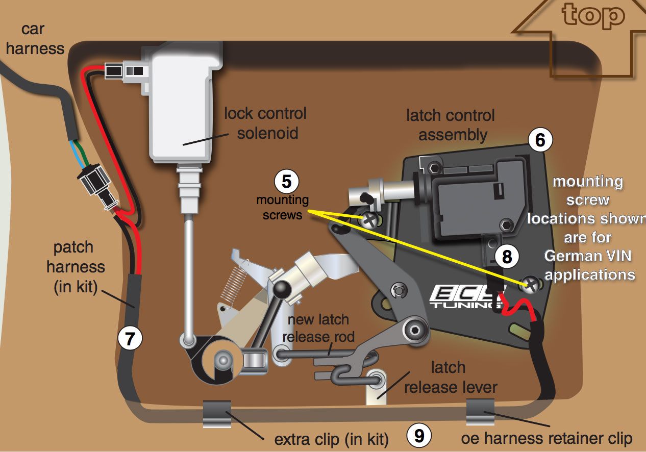
This schematic illustrates the factory installed components and their general locations inside the rear hatch.
We’ll concentrate on the components involved in the installation.
A voltage signal on the OEM wire harness (1) activates the lock control solenoid when the unlock button is pressed on the key fob.
The latch release rod (2) connects the hatch pull handle to the latch release lever. This will be replaced with the new latch release rod in the kit.
Press the two mounting grommets (3) in your kit into the factory holes in the hatch metal. These grommets will be used to mount your new latch release solenoid.

Special Note: On some early 1999-2000 Golfs, there is no hole for the lower grommet. If this happens, print out the template on page 16 of this pdf. Be sure to print it at 100%!
Mount the template as shown in the photo, temporarily locating it with the Torx head screw for the latch handle. Using the template, drill a new 5/16-inch hole and install the lower grom- met in the newly drilled hole.
Caution: Be careful as the drill bit breaks through the inner bracket. Do not let the bit strike the inner surface of the rear hatch outer skin or you may leave a dent that can be seen from the outside.
Preparing the solenoid module for installation
The rear hatch mounting grommet hole locations in German and Brazilian-made Golf hatches are slightly di erent. To accommodate these di erences, your ECS hatch kit mounting plate has extra mounting holes.
Start by identifying your car’s country of origin using the first three characters of the VIN (Vehicle Identification Number). This number can be see through the windshield on a plate mounted to the lower left hand corner of the dash.

If the rst three characters are WVW, the car is German-made. If the rst three characters are 9BW, the car is Brazilian-made.
The pivot arm stud in your new assembly ships in the Brazilian location.
If you are installing the assembly in a German-made Golf, loosen and remove the locknut on the back of the pivot stud. Re-locate the stud to the upper (German) hole, then reinstall the locknut and tighten it.

Install the New Release Mechanism
Here is the solenoid assembly with the pivot stud mounted in the default Brazilian mounting hole.
Note that the solenoid assembly mounting holes are elongated slots that allow sideways movement of the mechanism on the grommets. This allows the mechanism to be adjusted against the relay rod that connects the pivot arm to the latch release lever. See adjustment details on page 8.
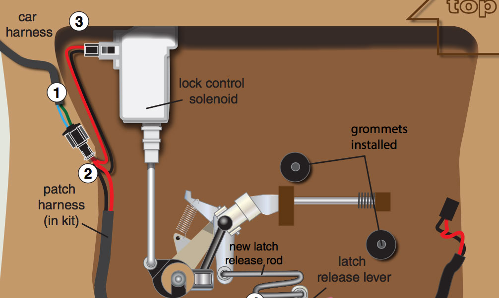
Unplug the car harness (1) from the lock control solenoid.
Connect the car harness (1) to the short side of the patch harness (2).
Plug the shorter lead from the patch harness into the lock control solenoid (3).
Remove the original latch release rod (see item 2 on page 4) and replace it with the new latch release rod in the kit (4).
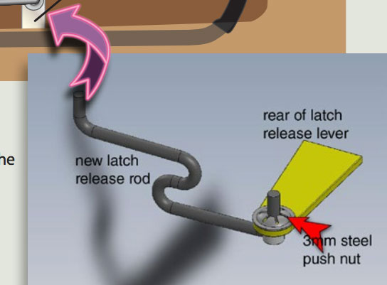
Your hatch pop kit includes a 3mm steel push nut.
When installing the new latch release rod, push the end of the rod through the white plastic grommet in the latch release lever. With the rod fully inserted, reach around from behind and press the 3mm push nut over the end of the rod to lock it in place, as shown in the illustration to the right.
Use the silver mounting screws (5) from the kit to attach the latch control solenoid assembly (6) to the grommets. Do not tighten the screws completely; just snug them enough that the assembly can still be shifted side-to- side on the grommets.
Run the long lead from the patch harness (7) along the edge of the stamped metal opening in the hatch, and plug it into the latch control solenoid (8).
Secure the patch harness to the edge of the opening in the hatch using the OEM harness clip and
the extra clip included in your kit (9).
Adjust the New Release Mechanism
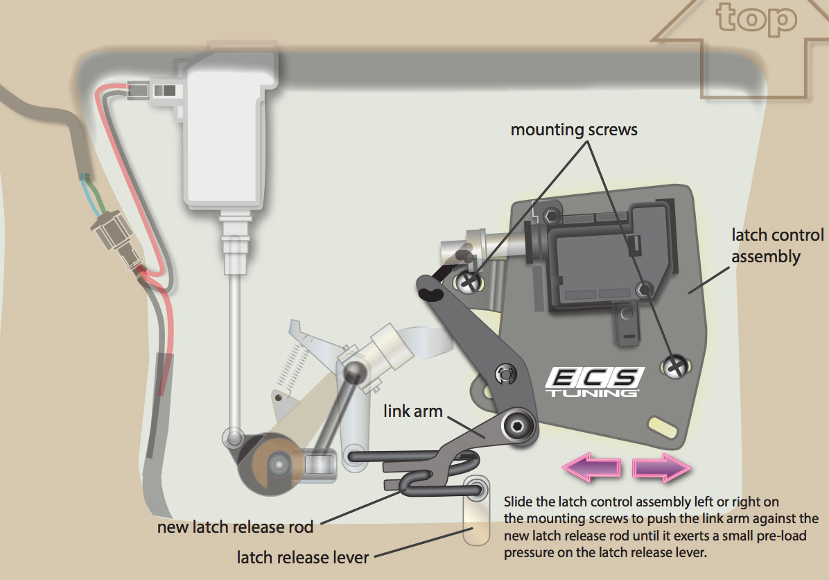
In this step, we will use
the elongated holes in the assembly to adjust the contact point for the linkage.
Proper adjustment ensures that the solenoid will move the linkage the correct distance to open the hatch.
• With the mounting screws just snug enough that the assembly can still be slid side-to-side, move the assembly laterally until the link arm just touches the new latch release rod. Then bump assembly a little farther in the same direction until the latch release lever just starts
to move. This slight pre- load ensures positive engagement and full latch lever travel.
• Tighten the screws so the adjustment will not change.
• Test hatch operation before reinstalling the interior trim, and adjust again, if necessary.
Install the Struts

CAUTION: Prop the hatch open with a rigid support that will not allow the hatch to fall on you as your remove the old struts and install the new ones.
Use a pick or small screwdriver to pry out the retainer clips at top and bottom that secure the ball sockets to the chassis studs.
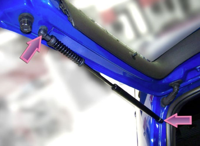
Your new struts come pre-assembled. Just push the open end of the each socket over the ball studs until they snap and lock in place.
Make sure the springs are located at the bottom with the door closed.
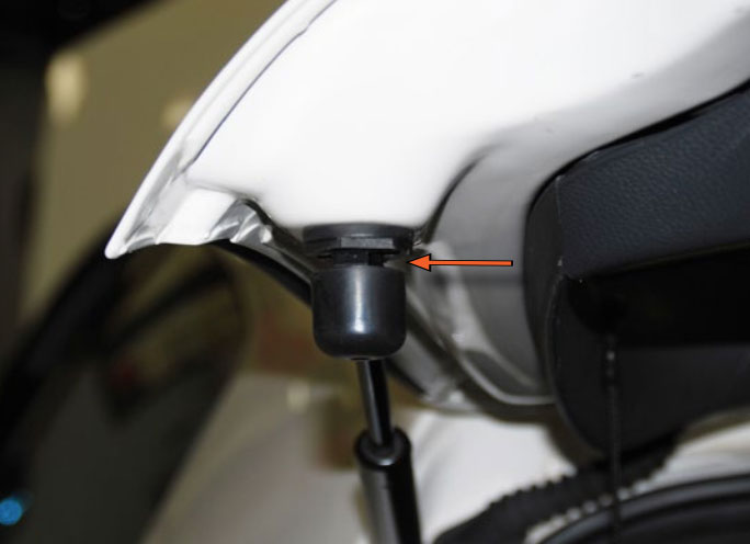
Install the Stop Bumpers

Remove the two original hatch bumpers by twisting them counter clockwise one quarter turn then pulling them straight out.
Unpack the new spring loaded bumpers. They should look like the picture on the left with the spring locked in the compressed position. If they look like this, skip the next step and continue with installing the bumpers. If they are extended like the picture below, then perform the next step before installaing the bumpers.

Push the bumper cap in until the spring is compressed, then turn it clockwise approximately one quarter turn until the cap is locked with the spring in the compressed position.

Install the two new bumpers into the hatch by pushing them in then turning them one quarter turn clockwise.

Insert a 3mm hex bit into the center of each new bumper until it engages the small screw inside, then loosen the screw approximately three complete turns. You will be able to see that the bumpers are loose and you can wiggle them back and forth.

Note the position of the spring bumpers. The depth of these bumpers is adjustable. The bumpers will be extended as shown in the picture. Also note the number of teeth that are exposed on the main shaft of each bumper (arrow).

Completely close, but DO NOT SLAM the hatch. Reopen the hatch and the bumpers will have adjusted themselves to the correct position. Note in this picture how the main shaft of the bumper has been pushed in and there are fewer teeth visible.
Tighten the 3mm screw in the center of each spring bumper. This will secure the bumper in the adjusted position.
Grasp each bumper cap and turn it counter clockwise.
The bumper caps will release and extend as shown in the picture. They are now completely adjusted and ready for use.
Test and Reassemble

CAUTION: The rear hatch will open VERY quickly when released. Stand clear as you press the hatch release button on the key fob.
Note: Your hatch can still be opened manually using the bayonet key and hatch release handle.
When you have tested hatch operation, snap the inner trim panel back in place and replace the two Phillips screws removed earlier.
This completes the installation of the ECS Tuning MKIV Golf/GTI Hatch Pop Kit.
Thanks for purchasing the ECS Tuning Hatch Pop Kit.
We appreciate your business, and hope this tutorial has been helpful and informative.
Interested in purchasing?
MK4 Hatch Pop Kit
Easy installation gives you access to your trunk with the touch of a button. No more struggling to open your hatch with your hands full!