Required Tools:
Flex Driver For Screw Type Hose Clamps*
Phillips Screwdriver
Torx T25 bit
Torx T30 bit
3/8” ratchet
1/4” ratchet with 6” extension
5mm Allen socket
Spring clamp pliers (or locking plier)
Schwaben VAG connector tool*
*Available at ECStuning.com
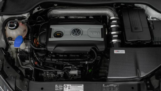
Before Installation, familiarize yourself
with the ECS Tuning MKVI 2.0T Carbon
Fiber Intake Kit

(1) Carbon Fiber Airbox
(1) Carbon Fiber Lid
(1) ECS Tuning High Flow Air Filter with clamp
(1) Carbon Fiber Air Filter Tube
(1) Carbon Fiber Turbo Inlet Tube
(4) Stainless Hose Clamps 65mm-89mm
(2) Stainless Hose Clamps 59mm-83mm
(5) 6mm Bolts with nylon washer 10mm long
(1) 6mm Bolt with large stainless steel
washer 15mm long
(2) Airbox grommets
(1) 3” Straight Coupler
(1) 3” Hump Coupler
(1) 2-3/8” Straight Coupler
(1) 4mm short Allen key
*Kit for CBFA adds:
(1) Filter for Secondary Air Pump
(1) Filter Clamp
-
ECS Tuning Aluminum Filter Adapter
1 Carbon Fiber Air Box and Lid
2 ECS Tuning High Flow Air Filter with clamp
3 Carbon Fiber Air Filter Tube
4 Carbon Fiber Turbo Inlet Tube
5 3” Straight Coupler
6 3” Hump Coupler
7 2-3/8” Straight Coupler
Step 1
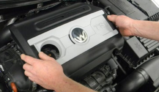
Remove the engine cover by
pulling up on the front two corners until
the front grommets release, then pull
up on the rear two corners until the rear
grommets release. Lift the cover off and
set it aside.
Step 2
Remove the two T25 Screws that
secure the original intake duct to the
radiator core support.
Step 3

Separate the intake duct from the adjoining
intake tube by pulling the two pieces apart.
Step 4

Disconnect the mass air flow sensor by
releasing the locking tab on the connector.
Use the Schwaben VAG connector tool
(ES2628676) to release the clip.
Insert the tool into the MAF connector as
shown, and gently pull back on the tool to
release the connector.
Step 5

Pull the mass air flow wiring harness out
of the retaining clip on the back of the
intake connecting pipe.
Position the harness out of the way.
Step 6

Fully loosen the 8 Phillips head screws
that hold the original air box lid to the
original lower air box.
Once loosened, these screws will remain
in the airbox lid. It is not necessary to
completely remove them.
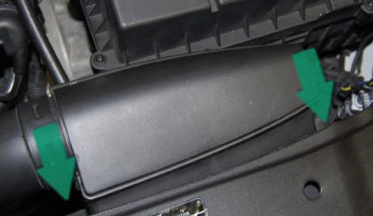
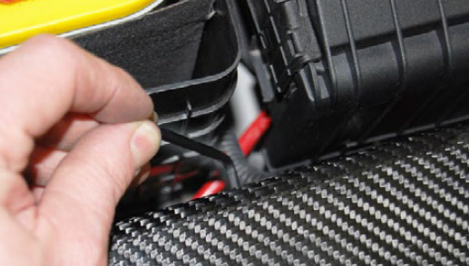
Step 7
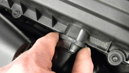
Remove the injection intake pipe by
squeezing the two tabs together
Step 8

Pull the air injection pipe off of the air box
lid, and set aside away from your
workspace.
Step 9
Using the special spring clamp pliers,
release the tension on the spring clamp
holding the connecting pipe to the main
intake tube. Slide the spring clamp onto
the connecting pipe and leave the spring
clamp pliers in place.
Tech Tip: If you do not have spring clamp pliers, you can use
channel locks or standard pliers to release the tension on these
clamps. If you do so, be very careful. The clamps can spring off
and cause serious personal injury or damage to your car.
Separate the connecting pipe from the
main intake tube by pulling it off the tube.
Step 10

Lift the airbox lid up and remove it with the
mass air flow sensor and connecting pipe
still connected.
Remove the spring clamp along with this
assembly, then carefully slide the spring
clamp off of the end of the connecting pipe,
and using extreme caution, release the
tension on the clamp.
Step 11

Using the same caution and method from
page 8, release the tension in the spring
clamp holding the connecting pipe to the
mass air flow sensor.
Step 12

Pull the connecting pipe and spring clamp
off of the mass air flow sensor.
Carefully slide the spring clamp off of the
connecting pipe, and using extreme
caution, release the tension in the spring
clamp.
Step 13

Using a T25 Torx bit, remove the two
screws holding the mass air flow sensor to
the original airbox lid.
Pull the mass air flow sensor out of the air
box lid.
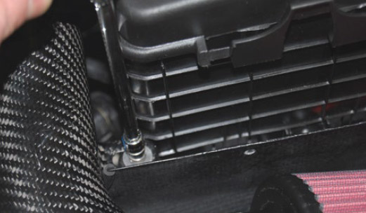
Step 14

Using a 5 mm Allen bit on an extension,
remove the bolt holding the lower air box in
place.
Step 15

Using both hands, lift up on the lower air
box to release the two insulating grommets.
Step 16
Pivot the lower air box around the coolant
air bleed hose and remove it from the car.
Step 17

Using a T30 Torx bit socket, remove the
bolt holding the main intake tube to the
heat shield in the rear of the cylinder head.
Step 18
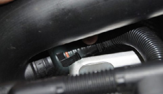
Remove the crank vent hose on the main
intake tube by pinching the release tabs
together using your thumb and forefinger,
then slide the hose off of the main intake
tube.
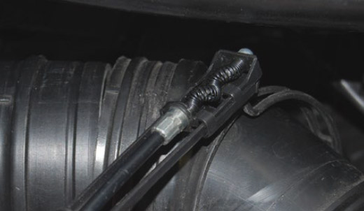
Step 19

Using the spring clamp (or locking)
pliers, release the tension on the clamp
holding the main intake tube hose to the
turbocharger.
Note: This clamp is difficult to access. This picture shows
the main intake tube removed for reference.
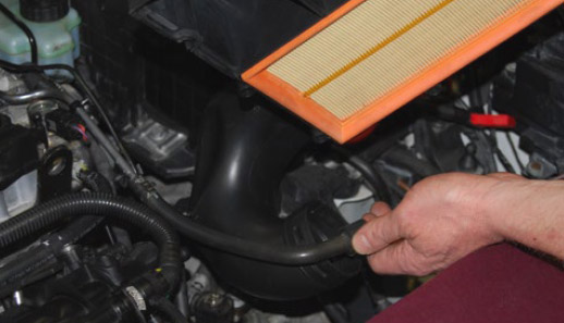
Step 20

Remove the main intake tube and hose by
pulling upward on the main intake tube.
Remove the clamp with this assembly.
Using caution, remove the spring clamp and
release the tension on the clamp.
Step 1

Slide the 2-3/8 straight coupler onto the
turbo end of the carbon fiber turbo inlet
tube.
Step 2

Install one of the 59mm-83mm hose clamps
on the top of the 2-3/8 coupler and tighten it
using a flex driver for screw-type hose clamps.
Use caution not to overtighten.
While the flex-driver is the preferred tool for
this step, a 7mm socket on an extension will
suffice. Take extra caution to avoid marring the
carbon fiber surface.
Flex Driver For Screw Type Hose Clamps
ES5013
Step 3

Place the other 59mm-83mm hose clamp
over the 2-3/8 coupler and install the turbo
inlet tube/coupler assembly onto the
turbocharger.
Step 4

Tighten the lower hose clamp using the flex
driver.
Tech Tip: Some brackets may be in hard to reach
places. You may wish to use a small socket or flex
driver tool for screw type hose clamps.
Step 5

Connect the crankcase ventilation hose by
pushing it into place on the turbo inlet tube.
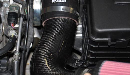
Step 6

Install the bolt holding the carbon fiber
turbo inlet tube to the heat shield on the
rear of the cylinder head.
Note: For Jetta GLI it may be necessary to adjust the
mounting tab on the heat shield approximately
20 degrees for proper clearance.
Step 7

Tighten the bolt using a T30 Torx bit socket
and ratchet.
Step 8

Place one of the 65mm-89mm clamps over
the end of the 3” hump coupler and push
the coupler onto the carbon fiber turbo inlet
tube.
Do not tighten the clamp at this time.
Note: Pay attention to the location/direction of the clamp
screw. All 4 clamps should be installed with the clam
screw in the same direction for ease of access as well
as uniform appearance.
Step 9

Connect the mass air flow sensor
connector to the mass air flow sensor by
pushing it on until you hear the faint “click”
with the connector locking tab engaging.
Step 10
Place one of the 65mm-89mm clamps over
the remaining end of the 3” hump coupler.
Push the mass air flow sensor into the 3”
hump coupler. Do not tighten the clamps
at this time.
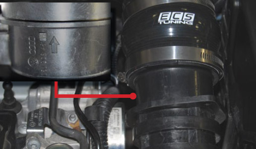
Note: Pay attention to the arrow on the mass air
flow sensor to make sure it is installed in the correct
direction. The arrow points in the direction of air
flow (to the engine).
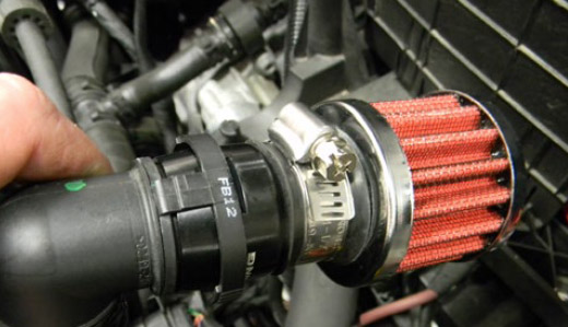
Step 11

Insert the secondary air pipe adapter into
the air pipe filter and tighten the clamp.
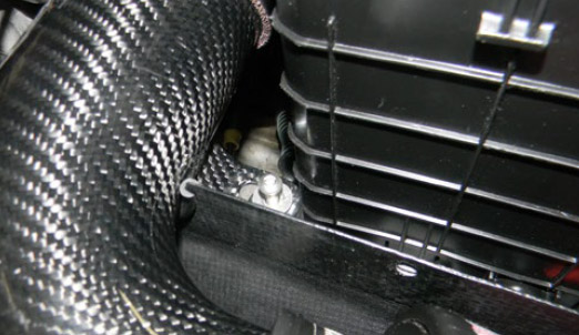
Step 12
Attach the air pipe filter and adapter to the
secondary air pipe, and secure
underneath the air box.
Note: You must choose an optimal location for the
secondary air pipe filter – the unit should be
supported such that it does not move around freely
in the engine bay, and has some access to air flow.
Our filter was secured under the airbox with a
zip-tie, proving to be an adequate location.
Step 13
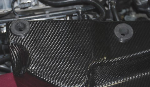
Install the 2 grommets into the bottom of the
carbon fiber airbox.
Step 14

Align the carbon fiber airbox and duct, and
push down on the carbon fiber airbox
until the grommets are seated in place.
Step 15
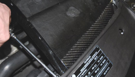
Using a T25 Torx bit, install and tighten the
two screws that secure the carbon fiber air
box duct to the radiator core support.
Tech Tip: A small amount of grease placed on the tip of
the Torx bit will hold the screws in place and keep them
from falling off.
Step 16
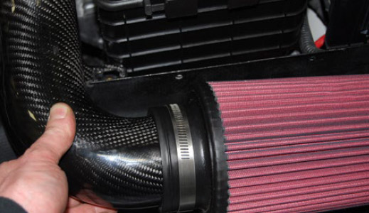
Slide the ECS Tuning high flow air filter
element with the clamp in place onto the
carbon fiber air filter tube.
Hold the air filter and tube in place in the
carbon fiber airbox to adjust the position
of the filter. Do not tighten the clamp at this
time.
Note: Use the mounting tab of the air filter tube as a
reference point in determining the correct location of the
filter. Make sure the air filter seam is at the bottom of the
filter.
Step 17
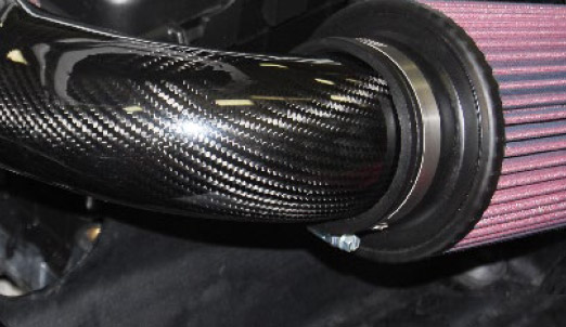
Lift the air filter and carbon fiber air filter
tube out and fully tighten the clamp on the
air filter.
Step 18
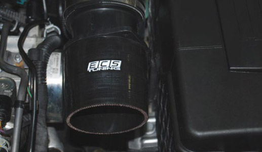
Install the 3” straight coupler onto the end
of the mass air flow sensor.
Step 19
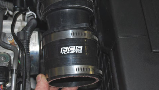
Place both remaining 65mm-89mm hose
clamps over the 3” straight coupler.
Do not tighten the clamps at this time.
Step 20
Insert the carbon fiber air filter tube into
the 3” straight coupler.
Step 21
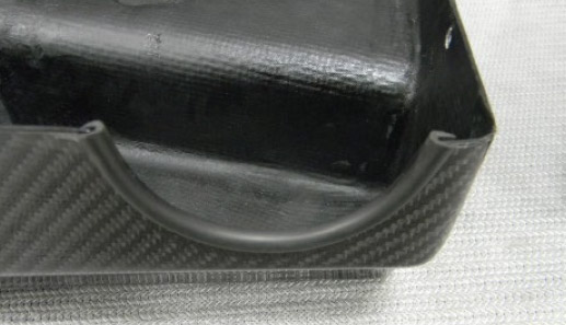
Be sure the Air Filter Tube to Air Box seals
remain in place during installation.
Step 22
Loosely install the 15mm long Allen bolt that
secures the carbon fiber air filter tube in
place.
Step 23
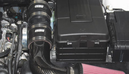
Carefully adjust the carbon fiber air filter tube,
the mass air flow sensor, and both couplers
so everything is aligned nicely and both
couplers are properly seated.
Tighten all 4 hose clamps, paying attention to
the alignment of the clamps in order to obtain
a clean and neat appearance.
Step 24
Tighten the air filter tube securing bolt and
stainless steel washer using a 4mm Allen
socket. A ratchet extension can be helpful
here.
Step 25

Place the carbon fiber airbox lid on top of
the carbon fiber airbox.
Be sure the Air Filter Tube to Air Box seals
are still properly in place during installation.
Step 26

Remove the battery cover by pushing the
release tab in the direction of the arrow on
the cover and lifting upwards.
Note: Removing the battery cover will allow you to more
easily access to the 2 screws on the back side of the
carbon fiber airbox lid.
Step 27

Loosely install all 5 Allen screws
with black nylon washers through the holes
in the carbon fiber air box lid, into the air
box.
Step 28
Using the included short 4mm Allen key,
hand tighten all 5 screws, securing the
carbon fiber air box lid to the carbon fiber
air box.
Be careful not to over tighten these screws,
or you risk cracking the carbon fiber or
stripping the threads.
Step 29