Introduction
Part Number: ES#3102387
The turbocharger – one of the easiest and most efficient ways to get horsepower out of your engine. It works great, but are you looking to get an “edge” on performance and get the most out of it? If so, our new ECS Tuning Turbo Blanket is the answer! How does it work? The expansion and flow of exhaust gas increases as it gets hotter, so keeping the heat in a turbocharger makes it work more efficiently. This is exactly what our ECS Tuning Turbo Blanket does, allowing the turbo to spool faster, resulting in decreased turbo lag. As an added benefit, under hood temperatures are reduced as well! Our turbo blanket is constructed with stainless steel hardware, double reinforced seams, a silica woven liner, and an aluminum pregnated glass outer shell, giving you the quality you expect from ECS Tuning.
Installation Overview
Turbo Blanket installation is simple in the way it fits, but you’ll be working in some fairly tight quarters, which may make the job seem difficult. The best advice we can give you before you start is to take your time. Don’t tackle it when you’re in a hurry or have a deadline. It’ll only take you a couple of hours or less, but patiently working the blanket in place until you access the snaps and safety wire is what takes the most time, and can be frustrating if you try to hurry.
Installing a safety wire is the final step, and a pair of safety wire pliers make it a lot easier. We’ll show you how they work, and we offer them for sale on our website as well. Thank you for looking to ECS Tuning for all your performance and repair needs. We appreciate your business!
During the first several heat cycles, the turbo blanket will smoke due to the curing process.

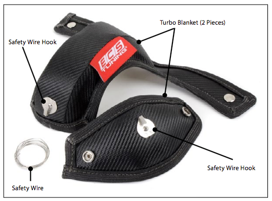
Kit Contents
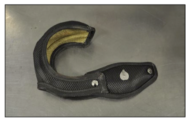
Use this photo for installation reference. It is possible that the safety wire hooks may rotate during shipment. Before you begin, be sure the safety wire hooks on your blanket are oriented as shown in this picture. Use the flat side on each hook base as an additional visual aid to orientation.
Required Tools
• Protecta-Sockets (for lug nuts): ES#2221243
• 3/8” Drive Ratchet: ES#2765902
• 3/8” Drive Torque Wrench: ES#2221245
• 3/8” Drive Deep and Shallow Sockets: ES#2763772
• 3/8” Drive Extensions: ES#2804822
• Hydraulic Floor Jack: ES#240941
• Torx Drivers and Sockets: ES#11417/8
• 1/2” Drive Deep and Shallow Sockets: ES#2839106
• 1/2” Drive Ratchet
• 1/2” Drive Extensions
• 1/2” Drive Torque Wrench: ES#2221244
• 1/2” Drive Breaker Bar: ES#2776653
• File Set
• Air Nozzle/Blow Gun
• Bench Mounted Vise
• Crows Foot Wrenches
• Hook and Pick Tool Set: ES#2778980
• Safety Wire Pliers: ES#3102852
• 1/4” Drive Ratchet: ES#2823235
• 1/4” Drive Deep and Shallow Sockets: ES#2823235
• 1/4” Drive Extensions: ES#2823235
• 1/4” Drive Torque Wrench
• Plier and Cutter Set: ES#2804496
• Flat and Phillips Screwdrivers: ES#2225921
• Jack Stands: ES#2763355
• Ball Pein Hammers
• Pry Bar Set: ES#1899378
• Electric/Cordless Drill
• Wire Strippers/Crimpers
• Adjustable (Crescent) Type Wrenches
• Drill Bits
• Punch and Chisel Set
• Hex Bit (Allen) Wrenches and Sockets: ES#11420
• Thread Repair Tools: ES#1306824
• Open/Boxed End Wrench Set: ES#2765907
Installation
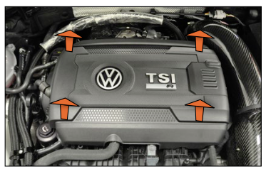
Step 1:
To begin with, you’ll need to remove the engine cover by pulling up at the four corners.
Step 2:
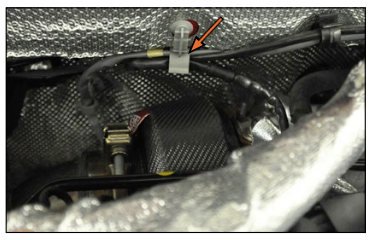
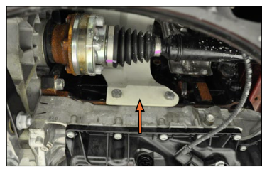
The turbocharger is located on the exhaust manifold near the firewall, and there is a heat shield above it. Locate the heat shield (arrow) then proceed to step 3.
We are installing this on a Golf R, but the overall procedure
is the same regardless of make or model. We also have our catch can kit installed on this car (the hoses that run along the firewall), but these are easy to work around if you have one too.

Step 3:
Inspect the picture on the right. This is the turbo heat shield off the car, positioned as it would be installed. It is held on at 5 locations, some of which are difficult to see with it on the car. Four Allen bolts hold it on along the bottom, and one nut secures it on the top of the turbocharger.

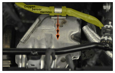
Step 4:
Now, back to the car. On the top of the heat shield, locate the oxygen sensor harness and pull it out of the spring clip.
Step 5:
10mm
Remove the nut on the top of the heat shield.

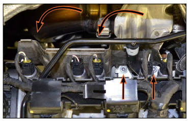
Step 6:
5mm Allen
Remove the four remaining Allen bolts, then remove the shield. You can see two of the bolts easily by looking straight down between the camshaft adjustment actuators. The other two are on the back side and more difficult to see, but you’ll find they are actually easy to get to.
Step 7:
Now, with the heat shield removed, you have access to the top of the turbocharger.
We recommend that you read through the end of these instructions before continuing with the installation. This will allow you to become familiar with the process and some of the tips and tricks that will make the job a lot easier.

Step 8:
We’re ready to install the blanket, but it’s difficult to show the remainder of the installation on the car, so we’re going to switch over to pictures with the turbocharger on a bench.
The overall installation is pretty simple. The blanket saddle naturally forms the shape of the turbocharger and slips down onto it from the top.
The two legs slide down between the turbo and cylinder head, straddling the exhaust runner.

Step 9:
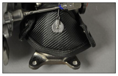
Once it is fully seated in place, you can see here how the blanket fits perfectly around the turbo.
Your car will have an oxygen sensor installed in the top of the turbo, which the blanket is designed to fit around.

Step 10:
The next step is to get underneath the car to access the bottom of the turbo. As shown here, you’ll see the legs of the saddle hanging down over the exhaust runner and the top safety hook along the back side. Each of the legs has a button snap on the end.

Step 11:
Wrap the blanket cinch strap the around the bottom of the exhaust runner and snap it onto the legs of the saddle. When installed correctly, the closed ends of the safety hooks will be facing each other.

Step 12:
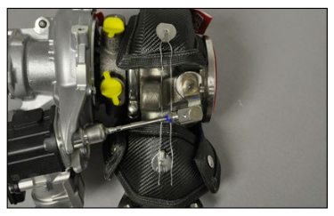
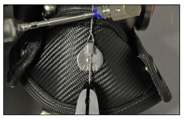
Now it’s time for the safety wire. First take a look at the installed wire. It runs between the two safety hooks, underneath the wastegate actuator rod. The goal of installing this wire is to hold the saddle and cinch strap together so they match the contour of the turbocharger as designed. The Turbo Blanket is designed to fit with an air gap between the blanket and turbo. It should NOT be installed tightly or with excessive force or strain on the wire, which would reduce its efficiency and weaken the safety hooks and the surrounding fibers of the blanket.
The only way to attain an effective, tight twist like the one shown in the picture is through the use of safety wire pliers, which we will use and demonstrate for this installation.

Step 13:
To install the wire, fold it in half, hang it over the top safety hook, run it underneath the wastegate actuator rod, then extend it over the bottom safety hook.
Only 12” of wire is required. If the included wire is longer, trim it to length before installing.
Step 14:
Using one hand, pull the saddle and cinch strap lightly together so they fit the contour of the turbo. Remember, the blanket is designed to work with an air gap between it and the turbo. Now grab both sides of the wire with the end of the safety wire pliers.

Step 15:
The key is to grab the wire approximately half way in between the bottom safety hook and the wastegate actuator rod as shown here.

Step 16:
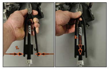
Lock the safety wire pliers onto the wire with the following procedure:
• Squeeze the safety wire plier handles together (you’ll have to squeeze fairly hard), until the retaining hook on the end of the handle is bottomed out.
• Holding the handles together, slide the chrome retaining sleeve downward.
• Holding the chrome retaining sleeve downward, release pressure on the handles.
Step 17:
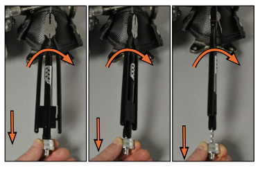
Grab a hold of the knurled chrome knob at the end of the pliers and pull it toward you. As you pull, the pliers will rotate and twist the wire.
When the knob will not extend any further, hold the pliers and release the knob. It will return into the plier body then you can twist the wire again.
Step 18:
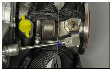
Continue to rotate the wire just until you have a nice even twist between the top safety hook and the end of the pliers. It is not necessary to create a tight loop where the wire attaches to the hook (see the loop at each safety hook in step 12).

Step 19:
Now release the pliers and extend the wire ends over the bottom safety hook.
Step 20:
Engage the pliers again and twist the wire until it is secure on the bottom safety hook. It is not necessary to create a tight loop where the wire attaches to the hook (see the loop at each safety hook in step 12).
If you experience trouble with the wire installation or need another piece, any basic mechanics wire will work.
Step 21:
Finally, snip the end of the wire so it does not snag or tear the blanket.
Step 22:
You may choose to reinstall the original heat shield or leave it off. If you leave it off, secure the oxygen sensor harness into the clip on the firewall.
Installation Tips
On some models such as this MK7 GTI, the lower insulation panel does not need to be removed. Others may have a full length panel or skid plate which you will have to remove for access from underneath.
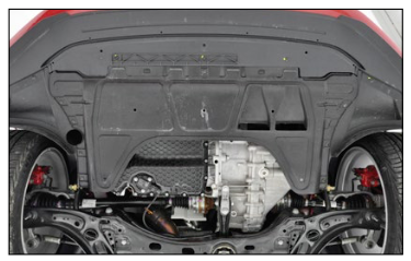
On FWD models, this RH inner CV boot shield is held on by two bolts and can be easily removed, providing additional access to the bottom of the turbo.
On some models, such as the Golf R, it is much easier to snap one side of the blanket together, then guide the other side through between the turbo and cylinder head.
It is ok to fold and flex the blanket lightly during installation, but keep it to a minimum. Excessive flexing of the fibers can weaken them, especially after the blanket has been heat cycled.
During the first several heat cycles, the turbo blanket will smoke due to the curing process.
Interested in purchasing?
ECS Tuning “HeatShield” Turbo Blanket