Introduction:
Part Numbers: ES#2903385, ES#2903383, ES#2903378, ES#2903361
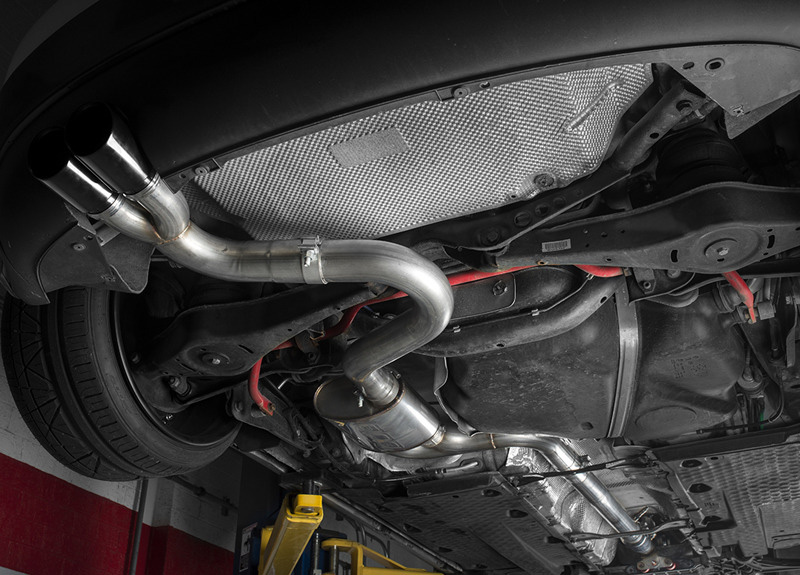
The ECS Tuning Valved Exhaust System for your VW MK5 GTI offers the following features:
• High-quality T304 grade stainless steel
• 3.0” mandrel-bent tubing
• Remote Controlled Exhaust Valve
• Fully adjustable exhaust tips, in Chrome or Black Chrome
• All installation hardware included
Upgrading the exhaust on your Volkswagen MK5 GTI is a very rewarding project that an experienced technician will be able to complete in a weekend, plan accordingly based on your experience level. The ECS Tuning performance exhaust system will fit the stock system, but will completely change the character of your car. Before you begin, read and familiarize yourself with these instructions and make sure you have all the required tools on hand. Thank you for purchasing your new Valved Exhaust System from ECS Tuning, we appreciate your business!

NOTE: The Cat-Back and Turbo-Back systems utilize a vacuum control valve. In order to install this vacuum control valve, you MUST either already have a Boost Tap installed on the vehicle, or one MUST be purchased prior to installation. The ECS Tuning Boost Tap can be found on http://www.ecstuning.com: ES#2718328.
Downpipe Kit Contents:

Cat-Back Kit Contents:

Turbo-Back Kit Contents:

Required Tools:
We recommend that you have a complete selection of tools and equipment necessary for automotive repair. Below is a list of the tools we used to install the ECS Tuning Valved Exhaust System. Additional tools may be required for any issues that arise during installation such as rust, corrosion, or broken and stripped fasteners.
• 3/8” Drive Ratchet: ES#2765902
• 3/8” Drive Torque Wrench: ES#2221245
• 3/8” Drive Sockets: 10mm, 13mm, 15mm, 16mm, 17mm, 18mm, 19mm: ES#11418
• Torx Drivers: T25, T30: ES#11417
• Triple Square Driver: M8: ES#9013
• Open/Boxed End Wrenches: 16mm, 17mm: ES#2765907
• Exhaust Hanger Remover Pliers: ES#2784927
• Oxygen Sensor Wrench: ES#240942
• VAG Connector Tool: ES#2628676
• Locking Hose Clamp Pliers: ES#2702616
Component Locations:

Installation:
Step 1:
Raise and safely support the vehicle.
Note: Please follow steps 1 & 2 regardless of whether you purchased a Cat-Back, Turbo-Back or Downpipe.

Step 2:
3/8” Drive Ratchet, 17mm Socket
Loosen the nuts (arrows) on the exhaust sleeve at the end of the downpipe/converter assembly. Slide the exhaust sleeve forward or backward on the exhaust pipe to separate the joint.
NOTE: If you purchased a Turbo-Back or Cat-Back system, please continue to the next step. If you purchased a Downpipe only, please skip ahead.

Step 3:
Exhaust Pipe Hanger Remover Pliers
Support the exhaust from below, then release all of the exhaust pipe hangers (except for the right rear muffler hanger) from the system. Please refer to the diagram earlier for all of the hanger locations.
Caution:
Enlist the help of a couple friends before lowering the system. It is very heavy and will require at least two people to safely remove it.

Step 4:
3/8” Drive Ratchet, 13mm Socket, Extension
Loosen the two bolts for the RR muffler hanger bracket, remove one bolt and leave the other bolt in finger tight.

Step 5:
While supporting each end of the exhaust, remove the finger tight bolt from the RR muffler hanger bracket. Ensure that the front joint is separated from the sleeve clamp, then lower the muffler assembly as one piece, with the RR bracket attached.

Step 6:
The RR hanger is not going to be used for the ECS Tuning Cat-Back system, but you must reinstall the RR hanger bolt, in order to secure the heat shield. Torque the bolt to 23 Nm (17 Ft-lbs).
Note: If you purchased a Turbo-Back system, please continue to the next step. If you purchased a Cat-Back system, please skip ahead.

Removing the stock downpipe–FSI:
Step 1:
Hose Clamp Pliers
Release the Spring Band Clamp for the Intake Air Duct and move it onto the end of the inlet for the Air Filter Housing, then pull the end of the Intake Air Duct forward to separate it from the Air Filter Housing.

Step 2:
VAG Connector Removal Tool
Disconnect the MAF electrical connector from the MAF sensor, then pop the two spring metal clips which hold the intake pipe to the Air Filter Housing, and pull the pipe away from the housing.

Step 3:
Grasp the Air Filter Housing and lift straight up one corner at a time to release the rubber mounting grommets from their mating pins on the engine. The photo to the right (showing the reverse side of the housing) is for reference, to demonstrate the location of the rubber mounting grommets.
Note: Be sure to pull on the housing as close to each grommet as possible during removal to prevent damage. We have found that it’s best to start by pulling up on the driver’s side front grommet, then the driver’s side rear, then the passenger’s side rear, and finally the passenger’s side front.

Step 4:
10mm Socket, 18mm Socket, M8 multi-point Bit
Remove the fasteners which secure the cover plate to the engine, they are difficult to see so a mirror may need to be used. Move the cover plate down off of the studs on the inside of the upper section, and then pull it straight out.

Removing the stock downpipe–TSI:
Step 1:
Remove the engine cover by carefully lifting upwards one corner at a time, then set the engine cover aside.

Step 2:
VAG Connector Tool
Disconnect the Mass Air Flow sensor electrical connector.

Step 3:
Locking Hose Clamp Pliers
Release the tension on the spring clamp that secures the flexible intake tube to the Mass Air Flow sensor.

Step 4:
Locking Hose Clamp Pliers
Pull the flexible intake tube off of the Mass Air Flow sensor.

Step 5:
3/8” Drive Ratchet, T30 Torx Socket
Remove the bolt securing the turbo inlet pipe to the heat shield, behind the rear of the cylinder head (shown here with the flexible intake tube removed for clarity).
Step 6:
Remove the crank vent hose from the turbo inlet pipe by pinching the retaining tabs together, then pulling it off of the pipe.

Step 7:
Locking Hose Clamp Pliers
Next we need to remove the turbo inlet pipe, to do so we need to release the tension on one of the two spring clamps, which are very difficult to see. It is easiest loosen the lower clamp on the turbo inlet pipe coupler, then pull the turbo inlet pipe and coupler off and set them aside.

Step 8:
10mm Socket, 18mm Socket, M8 multi-point Bit
Remove the fasteners which secure the cover plate to the engine, they are difficult to see so a mirror may need to be used. Move the cover plate down off of the studs on the inside of the upper section, and then pull it straight out.

Removing the stock downpipe–TSI & FSI:
From this point forward these instructions include both FSI and TSI equipped vehicles.
Step 1:
VAG Connector Tool
Unplug the front oxygen sensor connector, then remove the wiring harness from the two clips.

Step 2:
Oxygen Sensor Wrench, 16mm Wrench
Loosen and remove the front oxygen sensor, then loosen and remove the two upper nuts on the turbo outlet flange.
TECH TIP: Spray the oxygen sensor and the downpipe nuts with penetrating oil and allow the oil to soak in before attempting to remove them.

Step 3:
3/8” Drive Ratchet, 10mm Socket
Working from below the vehicle, loosen the four plastic shouldered hex nuts on the inner side of the right underbody panel.

Step 4:
VAG Connector Tool
Pull down the open side of the underbody panel to gain access to the rear oxygen sensor harness connection. Disconnect the connector, the easiest way to do this is to push in on the connector, release the locking tab, then pull the connector off. Remove the plug end from the bracket and release the wire from the clip.

Step 5:
Oxygen Sensor Wrench
Remove the rear oxygen sensor and set it aside.

Step 6:
Flat Blade Screwdriver, Torx Drivers: T25, T30
Remove the belly pan or skid plate from the vehicle, whichever you have installed. They are typically secured around the perimeter with 1/4 turn fasteners or Torx screws.
NOTE: If your vehicle is equipped with a CBFA engine you MUST remove the third oxygen sensor before continuing to the next step. The third oxygen sensor is located between the turbo outlet and the catalytic converter.

Step 7:
3/8” Drive Ratchet, 17mm Socket
Loosen and remove the two bolts which secure the CV axle shield to the engine, then remove the shield from the vehicle.

Step 8:
16mm Wrench
Loosen and remove the two lower nuts on the turbo outlet flange.
TECH TIP: Spray the nuts with penetrating oil and allow the oil to soak in before attempting to remove them.

Step 9:
3/8” Drive Ratchet, 13mm Socket
Support the rear of the downpipe/converter assembly with a jack stand or similar equipment, then remove the four nuts securing each chassis brace and remove them from the vehicle.
Step 10:
3/8” Drive Ratchet, 13mm Socket
Remove the two bolts which secure the downpipe bracket to the cross member.

Step 11:
To remove the downpipe from the vehicle, first, slide the converter off of the studs on the turbo outlet flange, then twist the downpipe counterclockwise approximately 90 degrees and pull the downpipe out of the vehicle.

Step 12:
Exhaust Pipe Hanger Remover Pliers
Remove the mounting bracket from the stock downpipe.

Installing the New Downpipe:
Step 1:
Please note that once the downpipe is installed and positioned properly, you must tighten the clamps, hangers, bolts, and nuts before continuing on. It is also EXTREMELY important that you support the downpipe components from below during this installation in order to eliminate the risk of damaging the flex connection. This can be easily achieved with jack stands, or you can have an assistant hold the system in place.

Step 2:
Carefully unpack your new downpipe and lay it out on the floor, locating everything in its installation position. At each of the slip connections, fit the pipes together to make sure they slide together easily. If they do not slide together easily, inspect the ends of the pipes for any slight distortion or bending (this is sometimes impossible to avoid during shipping). Using a ball peen hammer, gently tap on the ends of the pipes to straighten them and recheck fit. Once all of the slip connections slide together easily, proceed with the next step.

Step 3:
Place the new gasket onto the turbo outlet flange with the tab aligned on the bottom and facing towards the turbo housing.

Step 4:
Press the new downpipe bracket into the rubber mounts as shown.
NOTE: Please note that brackets must be installed in such a way that the curved edges of both the OE bracket and the ECS bracket will be on the top when installed on the vehicle.

Step 5:
Apply a small amount of the included “never-seize” paste to the threads on the included bolt before inserting it through the bracket and into the hole on the downpipe, then secure it with the nut. Be sure to leave the fasteners loose at this time.

Step 6:
Torque Wrench, 13mm Socket
Install the downpipe onto the turbo outlet in the reverse order of removal. Install the two bolts into the downpipe mounting bracket, then torque them to 25 Nm (18.4 Ft-lbs).

Step 7:
Torque Wrench, 16mm Socket
Install the four new nuts onto the turbo outlet flange studs, and torque them to 40 Nm (29.5 Ft-lbs)

Step 8:
Torque Wrench, 16mm & 19mm Sockets, 17mm Wrench
Apply a small amount of the included “never-seize” paste to the threads on the oxygen sensor sealing plug, then thread the plug and washer into the unused bung on the downpipe, and torque to 30 Nm (22.1 Ft-lbs). Tighten the bolt which secures the downpipe to the mounting bracket.
NOTE: If your vehicle is equipped with a CBFA engine this plug will NOT be used, simply install the third oxygen sensor in its place.

Step 9:
Slide the new exhaust clamp over the center pipe extension, be sure to orient the clamp so that the clamp bolt head faces as shown in the photo.

Step 10:
Slide the center pipe extension over the downpipe, twist the pipe if necessary to allow it to slide into place.

Step 11:
- Tighten the clamp on the center pipe extension.
- Reinstall the rear oxygen sensor.
- Reinstall the CV axle shield and the belly pan/skid plate.
- Reinstall the belly pan or skid plate on the vehicle.
- Reinstall the cover plate, front oxygen sensor, and MAF sensor.
- Reinstall the intake duct and engine cover.
Step 12:
If you purchased a Downpipe only, reinstall both chassis braces and install the provided exhaust pipe adapter and clamps as shown in the photo. Your installation is now complete.
If you purchased a Turbo-Back system, reinstall the front chassis brace only and continue with Installing the New Cat-Back
Installing the new cat-back:
Step 1:
Please note that during this installation, you will be installing the exhaust from front to back WITHOUT tightening any of the clamps, hangers, bolts, or nuts. Once the system is installed, we will then show you how to position the entire system properly, and then you will tighten the clamps, hangers, bolts, and nuts AFTER that is complete.
It is also EXTREMELY important that you support the exhaust components from below as you are installing the system. This can be easily achieved with jack stands, or you can have an assistant hold the system in place.

Step 2:
Carefully unpack your new exhaust system and lay it out on the floor, locating everything in its installation position. Leave the protective coverings installed so you do not scratch the mufflers or pipes. At each of the slip connections, fit the pipes together to make sure they slide together easily. If they do not slide together easily, inspect the ends of the pipes for any slight distortion or bending (this is sometimes impossible to avoid during shipping). Using a ball peen hammer, gently tap on the ends of the pipes to straighten them and recheck
At each of the slip connections, fit the pipes together to make sure they slide together easily. If they do not slide together easily, inspect the ends of the pipes for any slight distortion or bending (this is sometimes impossible to avoid during shipping). Using a ball peen hammer, gently tap on the ends of the pipes to straighten them and recheck fit. Once all of the slip connections slide together easily, proceed with the next step.

Step 3:
Spray each of the exhaust hangers with silicone spray lube in order to make it easier to install.

Step 4:
Slide the new exhaust clamp over the muffler inlet pipe, be sure to orient the clamp so that the clamp bolt head faces as shown in the photo.

Step 5:
Lift the muffler into the vehicle, then slide the pipe into place on the center pipe extension, leaving the clamp loose at this time. Insert the brackets into the rubber hangers (arrows), then support the muffler from below with jack stands or similar equipment.
NOTE: If you purchased a Cat-Back only, install the provided exhaust pipe adapter and clamps onto the downpipe/ converter assembly.

Step 6:
Insert the combination exhaust clamp/hanger into the rubber hanger on the vehicle, then slide the clamp end over the muffler outlet. Leave the clamp loose at this time.

Step 7:
Slide the tailpipe section onto the muffler outlet, twisting the pipe as necessary to allow it to slide on.

Step 8:
Slide the new exhaust clamp over the Y-Pipe, be sure to orient the clamp so that the clamp bolt head faces as shown in the photo. Slide the Y-Pipe hanger bracket into the exhaust hanger on the vehicle, then slide the Y-Pipe onto the tailpipe section, twisting the pipes as necessary to allow them to slide together.

Step 9:
3/8” Drive Ratchet, 15mm Socket
Rotate the tailpipe section downward and place each exhaust tip assembly (tip, integrated clamp, and adjusting insert) onto the end, but leave the adjustment clamps loose at this time. Rotate the tailpipe section upwards again, then proceed to the next step.

Step 10:
The most important part of these next few steps is patience. Begin here by orienting all of the exhaust hangers as shown in the photo. The exhaust hangers should be inclined toward the front of the vehicle so that lower hole is approximately 10-15mm forward of the upper hole, this will allow the hangers to pivot backward as the system heats up and expands.

Step 11:
Closely inspect the front of the exhaust system and check for clearances between the exhaust pipe and the chassis and drivetrain components. Pay close attention to where the pipe travels over the chassis braces.

Step 12:
3/8” Drive Ratchet, 15mm Socket
You can now tighten the forward exhaust clamps by hand until they are “snug”, but DO NOT USE AN IMPACT WRENCH and do not fully tighten them at this time. Next, inspect the middle of the exhaust system and check for clearances between the center section and the chassis and drivetrain/suspension components. Pay close attention to where the center section travels around the fuel tank.

Step 13:
3/8” Drive Ratchet, 15mm Socket
You can now tighten the rear exhaust clamps by hand until they are “snug”, but DO NOT USE AN IMPACT WRENCH and do not fully tighten them at this time. Finally, inspect the rear of the exhaust system and check for clearances between the pipe and the chassis and drivetrain/suspension components. Pay close attention to where the rear pipe travels around the rear cross member, and ensure that the exhaust tips are centered in the rear bumper cut-out.

Step 14:
3/8” Drive Ratchet, 13mm & 15mm Sockets
Once all of your adjustments are complete you can tighten all of the exhaust clamps. Adjust the exhaust tip so they are centered in the bumper cut out, then torque the clamps to 19 Nm (14 Ft-lbs).
Reinstall the rear chassis brace.
Your exhaust system installation is now complete, please continue to install the Remote Exhaust Valve Controller.
Remote Exhaust Valve Controller Kit:
Contents:

Remote Exhaust Valve Controller System Diagram:

Installation:
Step 1:
The Remote Exhaust Valve Controller allows the user to open and close the exhaust valve with the push of a button. It utilizes a vacuum valve that runs off of the vehicles vacuum system, and is activated by the included remote control switch.
NOTE:
In order to install this vacuum control valve, you MUST already have a Boost Tap installed on the vehicle if you do not have one they can be found on http://www.ecstuning.com: ES#2718328.

Step 2:
3/8” Drive Ratchet, T30 Torx Bit Socket
Remove the bolt which secures the oxygen sensor wiring harness bracket to the firewall near the brake fluid reservoir, then install the solenoid vacuum valve and the wiring harness bracket into place with the same bolt. DO NOT install the hose and check valve during this step.
NOTE: The check valve can be installed anywhere between the solenoid vacuum valve and the vacuum source. Take into consideration the amount of line needed between these components before cutting the hose to prevent excess waste.

Step 3:
If you do not currently have a Boost Tap installed on your engine, the ECS Tuning Boost Tap can be found on ecstuning.com: ES#2718328. If you already have a boost tap installed, measure the appropriate length of line required to connect the solenoid vacuum valve to one of the vacuum ports on the boost tap, then cut the line to that length. Install the supplied check valve in-line ANYWHERE between the valve and the boost tap, ensuring that the arrow on the check valve is pointed TOWARDS the boost tap.

Step 4:
If both of the vacuum ports on your boost tap are currently being used for other components, you can use the supplied “T-fitting” to splice into one of the vacuum hoses running from the boost tap. Using the photo for reference, cut the line and use the T-fitting to attach the vacuum line from the solenoid vacuum valve. Measure the appropriate length of line required to connect the solenoid vacuum valve to the T-fitting, then cut the line to that length. Install the supplied check valve in-line anywhere between the valve and the boost tap, ensuring that the arrow on the check valve is pointed TOWARDS the T-fitting.

Step 5:
Attach the vacuum line for the exhaust valve to the port on the solenoid vacuum valve. Route the line down away from any moving or hot components and out through the bottom of the vehicle.

Step 6:
Pull the vacuum line down through the opening in the subframe as shown in the photo, ensuring that the hose is clear of any moving or hot parts, including suspension, engine and exhaust components.

Step 7:
3/8” Drive Ratchet, 10mm Socket
Loosen the four plastic shouldered hex nuts on the inner side of the left underbody panel, then pull down on the open end of the panel and route the vacuum line underneath as shown in the photo. Reinstall the four nuts after the line has been routed.

Step 8:
Pull the vacuum line through the panel opening, run the line over the heat shield as shown in the photo, then attach the end to the vacuum port on the exhaust valve. Secure the line away from the exhaust with a plastic tie.

Step 9:
You have the choice of where to mount your control module, for this installation we chose to install it onto the battery cover. This can be achieved by drilling two 1/8” holes into the battery cover and attaching the control module with a plastic tie. If you choose to mount the control module somewhere else on the vehicle, you MUST ensure that it is protected from the elements, as well as any moving/hot components.
NOTE: DO NOT drill into the battery cover without first removing it from the vehicle, this will prevent accidentally drilling into the battery.

Step 10:
For this installation, we chose to wire our control module directly to the battery posts, to do so simply route the positive and negative wires toward the battery posts, then attach the wires using crimp-style ring connectors. You may choose to use a switched power source to supply power to the control module, this can be achieved by wiring the power supply to a switched 12V power source, such as the cigarette lighter.
NOTE: The signal wire (yellow) acts as the antenna for the remote controller, and remains unattached.

Step 11:
Plug the end of the wiring harness from the control module into the solenoid vacuum valve. Finally, perform a system check by starting the engine, then press the “unlock” button on the remote to open the valve, and press the “lock” button to close the valve. You should be able to hear a difference in both exhaust tone and volume when the valve is opened or closed.

Your MK5 ECS Tuning Valved Exhaust installation is complete!