Introduction:
Estimated Installation Time: 1.5-2 hours
Parts Required:
Brake pads
Brake rotors
ES#9069 – caliper-to-slide-pin bolts (replace) ES#1894565 – caliper carrier bolts
(torque to yield)

Tools We Used:
- brake piston retractor – ES#2153340 or ES#9747
- long-handled 1⁄2-inch ratchet
- torque wrench 1⁄2-inch drive
- lug bolt socket
- 21 mm open end wrench
- 15 mm open end wrench
- 13 mm box wrench
- 14 mm triple square socket
- T27 Torx driver bit
- RolocTM disk and die grinder
- impact driver – ES#11416
Notes:
The brake caliper piston retractor is a must-have tool for this project. You cannot squeeze the pistons back in place with a c-clamp or large adjustable pliers as you would on the front brake calipers. They must be screwed back into the caliper. ECS sells two professional grade brake piston retractor kits: ES#9747 and ES#2153340.
Roloc disk mandrels are great for cleaning the wheel hub. They can be chucked up in an electric or air drill if a die grinder is unavailable. Roloc disk kits are available at many auto parts, home improvement, and hardware stores.
The impact driver is not essential but does a great job of removing frozen rotor hold down screws, with less risk of rounding out the screw heads.

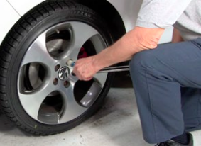
Step 1:
Our procedure begins with the rear road wheel/tire already removed.
Remove the brake caliper.
Use a 15 mm backing wrench, hold the hex head on the caliper slide pin as you loosen and remove the top M8 caliper-to-slide pin retaining bolt using a 13 mm box wrench (or socket, if you prefer).
Remove the lower caliper-to-slide pin bolt the same way.


Step 2:
Remove the caliper and pull it away from the caliper frame. If it is tight against the backs of the brake pads, you may need to lever it off the frame using a large screwdriver or other prying tool placed between the caliper and caliper frame.

Step 3:
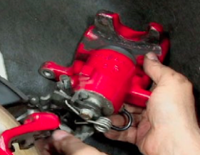
Inspect the handbrake mechanism on the back of the caliper. Look for damaged, loose, or corroded parts. The mechanism should be free enough that you can rotate it against its counter spring, by hand.
Inspect the handbrake cable as well. Stop here and repair any damaged parts or cables before proceeding.
Step 4:
Caliper piston retractor kits include a screw press, a push plate, and several retractor disks in different diameters to match various caliper piston sizes.

Step 5:
Each retractor disk has two holes that engage pins on the screw press, and two raised pins that engage recessed notches in the caliper piston.
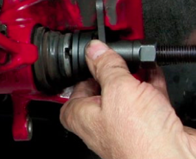
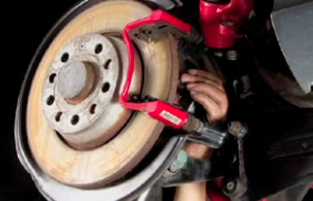
Place the retractor tool inside the caliper body, as shown. Screw the adjustment collar outward until the press plate contacts the caliper body. Hold the collar steady to keep it from turning as you turn the screw jack to rotate the piston inward.

Raised retractor tool pins engage the notches in the piston head. This rotates the brake caliper piston back into the caliper bore as the jack screw is turned.
Make sure the piston is screwed all the way in to make room for the added thickness of the new pads or you won’t be able to reinstall the caliper.
Step 6:
Don’t let the caliper hang from its rubber brake hose. Use a bungee cord or length of wire to properly support its weight.

Step 7:
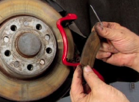
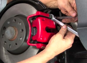
Pry the brake pads from the caliper frame using a pick or thin-bladed screwdriver. These pads are shot.
Step 8:
The caliper frame must be removed before we can remove the brake rotors. The caliper frame has two tasks: it holds the brakes pads in place and supports the brake caliper.
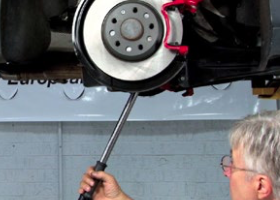
This photo shows a 14 mm triple square driver and long handled ratchet next to a caliper frame. Note the long attachment bolts. These are torque-to-yield bolts and should be replaced.

Step 9:
Working from the back of the caliper frame, loosen and remove the attachment bolts and the caliper frame.
The bolts will be tight; hence the long handled ratchet.
Step 10:
Remove the rotor set screw. We prefer using an impact driver with our Torx bit, instead of a ratchet.
Striking the impact driver pushes the Torx bit tightly into the screw socket and turns it at the same time. is reduces the chances of stripping the screw head, a common problem, especially if the screw is rusted in place.

Step 11:
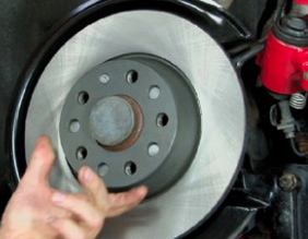
Pull on the rotor. Clean the wheel hub surface to remove dirt and rust.
A Roloc abrasive disk mounted in a die grinder makes fast work of this task.
You can also mount the Roloc disk mandrel in an electric drill and get similar results.

Step 12:
Install the new rotor after cleaning it with brake cleaning spray or with soap and hot water. We don’t want any oil or other contamination on the rotor braking face.
Install the hold down screw.
Step 13:
Reinstall the brake caliper frame. Use new bolts. (ES#1894565).
Torque the caliper carrier attachment bolts to 90 Nm (66 ft-lb) plus 90 degrees.
Step 14:
Carefully apply a small amount of brake assembly lube to the pad sliding surfaces at the caliper frame. ECS Tuning stocks an assortment of professional grade brake assembly lubrication products from name brand suppliers.
Install the new pads, being careful not to get any oil or greasy fingerprints on the brake friction lining. Press them tight against the rotor.

Step 15:
Reinstall the caliper. Reverse what you did to remove it. If you have the piston fully retracted, it should t over the new pads and slide into place.

Step 16:
Align the holes in the caliper frame with the slide pins. Push the new M8x22 caliper bolts through the caliper frame holes and screw them into the slide pin threaded holes.
Hold the slide pin hex with a 15 mm open end and tighten the bolts with a 13 mm wrench to 35 Nm (26 ft-lb).
Repeat this step on the lower caliper attachment.

Step 17:
Repeat the steps we have already covered on the on the other side of the vehicle.
Reinstall the road wheels and torque the lugs, tightening in a star pattern to 120 Nm (89 ft-lb).
Final Notes:
- Very important. After lowering the car and reinstalling the road wheels, pump the brake pedal several times to properly position the caliper pistons against the pads.
- Check handbrake operation, both apply and release.
- Check and correct the fluid level in the brake master cylinder.
Click HERE to shop now for Rear Brakes