Click HERE for Printable PDF
Part Number: ES#2609354
Introduction
What Is FSI?
FSI stands for Fuel Stratified Injection, a high-pressure injection system that sprays atomized fuel directly into the cylinders. This requires much higher pressures than those found in previous port-injection systems that normally operate at fuel rail pressures of 40-60 psi. Fuel pressure at the FSI injector tips typically varies between 30 and 110 bar (435-1600 psi). That’s no typo.
How Does the High-Pressure Pump Work?
The high pressures needed for FSI injection come from a piston pump that is bolted to the cylinder head and actuated by camshaft lobes. The pump body contains a pressure sensor and electrically-operated fuel pressure regulator. This feedback loop matches pump pressures to driving conditions.
What Goes Wrong?
The pump rod is actuated by the camshaft pump lobes. A cup-shaped cam follower separates the end of the pump shaft and the cam. Wear at the contact point between the camshaft lobe and cam follower reduces pump lift and pressure, resulting in engine fuel starvation, especially noticeable when fuel demands are highest, such as cold start and acceleration modes.
What Is the Fix?
Assuming the camshaft is not damaged, replacement of a moderately worn camshaft follower can restore normal pressures. VW/Audi has manufactured new camshafts with harder cam lobes. Please check for the latest parts information before ordering any camshaft, to ensure installation of the correct replacement part.
In cases of extreme wear, replacement of the pump, follower, and camshaft will be required to restore normal pump operation. If the cam follower has worn through or has a concave face, odds are additional repairs will be needed.
Symptoms:
Along with poor engine performance, symptoms include an illuminated MIL with Diagnostic Trouble Codes (DTCs) stored in memory.
Common DTCs include:
P2293 (Fuel Pressure Regulator 2 Performance)
P0087 (Fuel Rail Pressure Low)
P1093 (Fuel Trim 2 Bank 1 Malfunction)
Today’s project car is a 2006 Audi A3 with 120,000 miles on the odometer.
Let’s dive in.

This illustration shows fastener, electrical connection, and fuel line attachment points for the FSI fuel pump. Please refer to this image as we walk you through the photo tutorial showing how to replace the fuel pump camshaft follower.
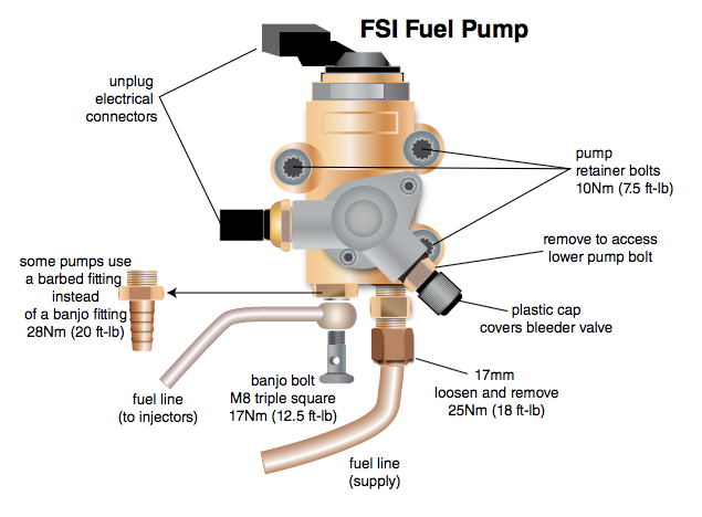
The factory installed pump may have either a barbed fitting or a banjo fitting at the high-pressure port. If the fitting on your new pump does not match the fuel line in your car, transfer the correct fitting from the old pump to the new one.
Installation:
Step 1:
Start with the engine cool.
Squeeze the spring clamp on the air inlet hose to loosen it and remove the hose from the engine cover/ filter housing.

Step 2:
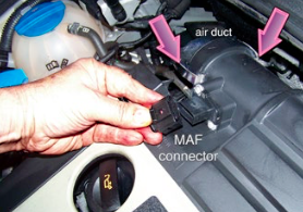
At the right rear of the air intake housing, unplug the mass air ow sensor (MAF) connector.
Pop the two metal spring clips (arrows) that hold the air housing outlet duct in place, and pull the duct away from the housing.
Grab the air intake/ filter housing and lift the cover straight up to release its rubber mounting grommets from the mating mount pins on the engine.
Step 3:
This photo is for reference. It shows the location of the rubber mounting grommets (arrows) with the air filter housing removed and flipped over.
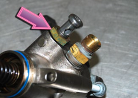
Step 4:
Unplug the electrical connectors from the pump pressure regulator and pressure sensor (arrows).

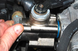
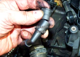
Step 5:
Disconnect the vacuum hose from the vacuum pump nipple located next to the fuel pump.
Pull the line aside to make room. Don’t lose the rubber grommet that is between the line and nipple.
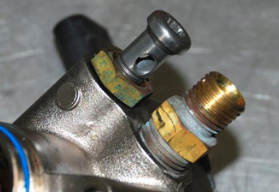
Step 6:
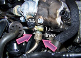
Remove the black plastic vent cap. Place a rag beneath the valve beneath it and use a small punch or screwdriver tip to gently depress the center of the Schrader valve to bleed any fuel remaining in the pump.
Note the location of the two fuel lines at the bottom of the pump.
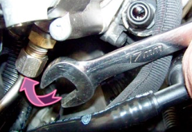
Step 7:
Use a 17mm open end or flange nut wrench to loosen the fuel line attachment collar. Slide the collar away from the fitting.
Step 8:
On pumps that use them, the banjo bolt fitting for the other fuel line is less accessible.
If all you have is an M8 hex-head driver and long extension, it is possible to remove the bolt. Awkward, but possible.
A stubby M8 triple square bit with a 10mm hex shank fits into this tight space more easily and can be turned with a wrench. (If you have a 10mm box ratchet, this goes a lot faster.)
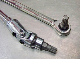
Step 9:
Removing and installing the banjo bolt is the toughest part of the job. The short bit and box wrench provided us with a secure grip on the bolt, and enough leverage to break it free.
Remove the banjo bolt and set it aside.

Step 10:
Using a 13mm box wrench, loosen and remove the brass test port. This gives you better access to the lowest of the three pump bolts.

Step 11:
Using a T30 Torx bit, loosen and remove the three pump bolts. (Your cam follower comes packaged with new bolts.)

Step 12:
Remove the pump. If it has been in place for a while, the sealing ring may be heat-hardened, and stick in the pump bore.
We needed to tap the pump gently with a plastic mallet to break it free.

Step 13:
Remove the old o-ring and install the new one from the kit (arrow). Clean the groove in the pump body, as needed.

Step 14:
Very Important: Make sure the banjo bolt and brass fitting threads are clean and free of burrs. This is a fine thread fitting, and it will be easy to cross thread the banjo bolt during installation when it is hard to reach.
You should be able to thread the bolt in several turns by hand.
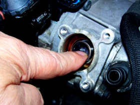
Step 15:
Reach in with your fingertip and slide the old cam follower out of the pump bore.
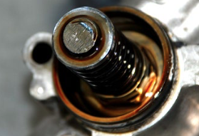
Step 16:
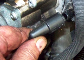
Cam follower condition varies. This photo shows
a new follower next to one that is has been worn through. Others will exhibit wear somewhere between these extremes, with a slightly convex wear pattern in the follower’s face. If the black anti-wear coating is gone, replace the follower.
Clearly, periodic inspections are a good idea if you want to avoid this situation.

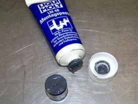
Step 17:
Oil the circumference of the new follower and apply a generous coating of assembly lube to the face of the cam follower. This will prevent a “dry start” and surface galling when the engine first starts.
Step 18:
Slide the new follower into the bore.

Step 19:
Reinstall the pump on the engine. Use the new pump bolts in your kit. Do not tighten any one bolt all the way initially. Instead, alternately tighten each bolt to draw the pump evenly against the engine.
Final torque is 10Nm (7.5 ft-lb).
Re-attach the fuel lines and electrical connectors, and reverse your steps to complete the job.
Cautions and Assembly Notes:
Inspect the camshaft and pump rod for damage. If the follower is worn through, there is a good chance that both the camshaft lobe and pump shaft have been galled and damaged, requiring replacement of one or possibly both.
This pump is severely galled and will be replaced. Do not reuse a pump in this condition. Check camshaft lobes for signs of similar damage.
When screwing the banjo bolt in, be very careful not to cross thread it. Due to its awkward placement at the base of the pump, it is very easy to get it cocked to one side as you thread it in.
Make sure to thread the banjo bolt in by hand at least 4-5 full threads before using your wrench.
There are no sealing washers to replace at the banjo fitting.
If the rubber sealing grommet at the vacuum pump hose sticks on the pump nipple, remove the grommet from the pump and insert it into the hose first. Makes it a lot easier to reinstall the hose.
If you start the engine to check for leaks with the air filter housing off the car, expect to throw a MAF sensor DTC that illuminates the MIL.
Don’t worry, after you install the air cleaner housing and reconnect the MAF, the PCM will turn the MIL off and erase the DTC in a few drive cycles.

Click HERE to purchase a Cam Follower
This tutorial is provided as a courtesy by ECS Tuning.
Proper service and repair procedures are vital to the safe, reliable operation of all motor vehicles as well as the personal safety of those performing the repairs. Standard safety procedures and precautions (including use of safety goggles and proper tools and equipment) should be followed at all times to eliminate the possibility of personal injury or improper service which could damage the vehicle or compromise its safety.
Although this material has been prepared with the intent to provide reliable information, no warranty (express or implied) is made as to its accuracy or completeness. Neither is any liability assumed for loss or damage resulting from reliance on this mate- rial. SPECIFICALLY, NO WARRANTY OF MERCHANTABILITY, FITNESS FOR A PARTICULAR PURPOSE OR ANY OTHER WARRANTY IS MADE OR TO BE IMPLIED WITH RESPECT TO THIS MATERIAL. In no event will ECS Tuning, Incorporated or its a liates be liable for any damages, direct or indirect, consequential or compensatory, arising out of the use of this material.