
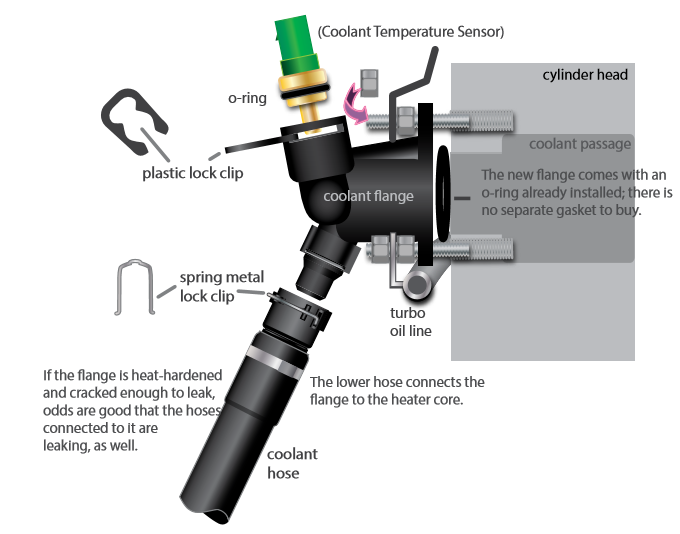
The coolant flange located at the rear of the Audi 1.8T cylinder head is the source of several common coolant leaks. Made of plastic, it bolts to the head with two threaded studs. In addition to holding the coolant flange in place the studs support a pair of tubing brackets, including a stand-off bracket for the turbo oil line.
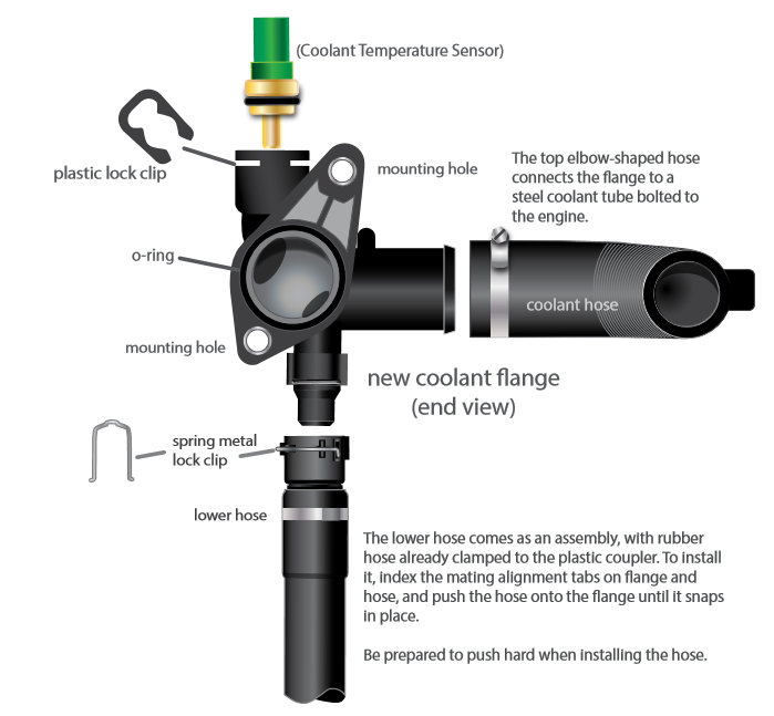
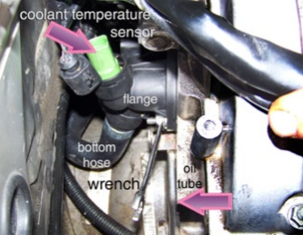
• The flange supplies coolant to two coolant hoses, and houses the Coolant Temperature Sensor. The Coolant Temperature Sensor is held in place by a u-shaped plastic lock clip and sealed with an o-ring.
• The lower coolant hose has an integral sealing ring. The hose slides onto the lower flange neck, and snaps in place, retained by a metal spring clip that engages mating grooves in hose neck and flange.
• Here’s a right angle view of the same coolant flange, showing the two mounting holes for the head studs. Note the elbow-shaped hose to the right. This hose connects the flange to a steel coolant tube.
• Spend extra time cleaning the mating surface at the rear of the cylinder head where the flange mounts. The flange o-ring needs a clean, flat surface to seal properly.
A spring clamp tool makes removing and installing spring-style hose clamps a breeze. Attach the tool and squeeze the handle until it locks in place to expand the clamp. That leaves both hands free to slide the clamp off and on.
A correct mixture of pure coolant and distilled water is essential for adequate freeze/boil-over protection and chemical protection against rust, corrosion, and harmful deposits. A refractometer is the most accurate tool for measuring mix ratios.
Refilling the cooling system can be accomplished without special tools, but we prefer a vacuum refill tool. Just insert the tool’s rubber cone into the coolant jug neck and connect the tool to shop air. Switch the valve to pull a vacuum in the system, then move the valve to “fill” and let the vacuum in the system suck fresh pre-mixed coolant into the system from a container.


Kit Contents
Your Coolant Flange Kit with Coolant (ES2602886) includes: a new coolant flange with o-ring; attachment studs; an engine Coolant Temperature Sensor with o-ring and plastic retainer clip, and two quarts of pure coolant.
We have listed related, optional items, available separately, and recommend them for a leak-free repair. These include the two hoses attached to the flange, and a bottle of cooling system flush. If you are replacing a coolant flange for a leak, expect to find one or both of the hoses at the end of their service life.
You may also find an unpleasant accumulation of sludge and rust in the system, as we did, so be prepared, especially if the system has been neglected.
Note: Depending on whether you car has been apart before, you may need to purchase one or more worm style hose clamps of different sizes to complete this job.
Under the car – Step 1

• Remove the expansion tank pressure cap.
• Raise the car and remove the belly pan.
• Drain the coolant.
• Open the bleeder at the base of the lower radiator hose (arrow) by turning it counterclockwise until the coolant flows freely. (see next slide)
Under the Car – Step 2

You may need pliers to turn the drain plug if it is stuck. If it is really stuck and feels like it might break, you can pull the clip on the temp sensor (arrow) and remove it to drain the coolant. Replace the sensor o-ring if you take this route.
To avoid spilling coolant all over, attach a length of flexible plastic tubing to the drain outlet nipple as you open the drain-cock. This will direct the coolant flow to a catch can, as we’re doing here.
Close the drain when the flow stops. Hand tight will do.
Under the Hood – Step 3

The coolant flange is located at the rear of the engine, on the rear vertical face of the cylinder head (location indicated by our arrow).
Clearly, we need to remove several items to reach it.
Under the Hood – Step 4

Turn each of the three cross-slotted beauty cover retainer clips a quarter turn to release them; lift off the cover.
Under the Hood – Step 5

Components to remove from the right side of the engine include: two metal tubes, a turbo oil line, and a metal heat shield.
We have highlighted their general location in blue.
Under the Hood – Step 6

• Loosen the hose clamps at either end of the crankcase vent tube.
• Using a 5mm driver, remove the hex head bolts holding the tube to the valve cover.
• Disconnect the valve from the hoses at either end and remove it.
Under the Hood – Step 7

Pull the oxygen sensor harness from the retainer clip on the heat shield.
Under the Hood – Step 8

Use an 8mm short socket and ratchet to remove the four retainer bolts from the underside of the heat shield.
Under the Hood – Step 9

Lift out the heat shield.
Under the Hood – Step 10

Remove the hex head bolts holding the combi-valve tube/purge line tubes to the valve cover.
Under the Hood – Step 11
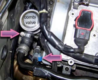
Remove the clamps from the hose at the combi- valve and the hose in the purge line next to it (arrows). Our car has worm clamps already installed, yours may have a factory crimp-style clamps that must be cut off and replaced.
Under the Hood – Step 12

Disconnect the tubes and hoses.
Under the Hood – Step 13

Pull the vacuum hose from the combi-valve.
Under the Hood – Step 14

Using a 5mm hex key, unbolt the combi-valve assembly from the back of the head.
Under the Hood – Step 15

Note the location of the combi-valve bolts and thin stamped metal gasket. The gasket will slide off easily, so don’t drop it behind the engine as you remove (or reinstall) the valve.
Under the Hood – Step 16

With the combi-valve out of the way, we can see the flange at the rear of the cylinder head. There are multiple coolant leaks and everything is coated with coolant crust.
As you can see, it’s a tight fit back here, with a only a few inches separating the firewall and engine.
Under the Hood – Step 17

Rather than fight with the Coolant Temperature Sensor electrical connector in tight quarters, pop out the plastic retainer clip with a pick or screwdriver and pull the sensor out of the flange, wiring and all.
Under the Hood – Step 18

Pulling the sensor up makes it easier to unplug. Press on the release tab and pull at the same time to separate the black electrical connector from the sensor.
CAUTION: Inspect the electrical contacts inside the connector for signs of corrosion. Clean with a spray contact cleaner, if necessary. This is a high priority sensor, and the connection must be a good one.
Under the Hood – Step 19

If you are re-using the lower hose, reach down and slide the metal clip out of the plastic collar until it hits the stops. Wiggle the hose free from the flange.
Using a 10mm box wrench, remove the two 6mm nuts from the flange studs.
NOTE: The retaining nuts secure tubing support brackets at top and bottom. The flange will not move, even with both nuts removed. The studs must be removed separately.
(See next step for additional photo.)
Under the Hood – Step 20

Here’s a bank shot photo taken with a mirror so you can see the retainer nut on the flange stud. The lower bracket shown here supports the turbo oil tube.
There is another, similar nut on the top flange stud that holds a purge line bracket.
Under the Hood – Step 21

Before we can pop the oil tube bracket off the lower flange stud, we need to remove the two retainer bolts securing the oil tube to the side of the engine. Remove them both with a 6mm hex driver and ratchet (arrow).
When the tube is free, you can slide the tube rearward far enough to pop its support bracket off the lower flange stud.
Remove the upper nut and pull the upper bracket off its stud.
Under the Hood – Step 22

Move to the left side of the flange. Follow the long metal coolant tube rearward to the rubber hose (arrow) that connects the tube to the coolant flange.
Disconnect the hose from the flange.
Under the Hood – Step 23

The old hose is tired, and a squeeze with thumb and forefinger tell us it is mushy at the bloated spot indicated by our arrows.
Note: This is another case where you may need to purchase a new worm clamp to replace the factory crimp clamp after you cut it off (right arrow).
Under the Hood – Step 24
Now we can unbolt the flange and remove it. Using a 10mm wrench, we unscrew both threaded studs and pull the flange.
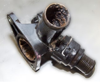
Note: The lower hose on our car was leaking so badly that we just slit the rubber and pulled it off, leaving the coupler on the flange.
Ugh. One look inside the flange tells us that this system needs to be flushed to remove these heavy deposits.
Under the Hood – Step 25

The coolant jug tells a similar story. We remove it from the car and flush it with a garden hose.
Under the Hood – Step 26

We will preinstall the lower hose on the flange. Working on the bench makes it a lot easier to push the new hose coupler onto the flange until the coupler clip snaps in place.
If you are reusing the old hose, you’ll have to make this connection after the flange is installed on the engine.
Under the Hood – Step 27

We will also preinstall the Coolant Temperature Sensor.
Slide the new o-ring onto the Coolant Temperature Sensor. Then push the sensor into the flange until you can slide the plastic retainer clip all the way in, as shown.
Slide the nutted-studs into the mounting holes.
Under the Hood – Step 28
Clean the flange mounting area.
Install the assembly. Hand thread both nutted-studs through the flange holes into the head. Alternately tighten both to clamp the flange evenly.
Plug in the sensor connector, until it locks in place.
Reinstall both brackets over the nutted-studs and secure them with the 6mm nuts.
Refer to the illustration of page 2 if you need a refresher on component locations.
Finishing Up

Now you can start re-assembling the parts removed earlier.
Here are a few additional suggestions that may make the job go easier, and prevent future problems.
Flushing

If the inside of your cooling system looks like this, take the time to flush it out with a chemical cleaner. (DEI Cooling System flush is available from ECS Tuning – ES2608077)
Mix your fresh coolant using distilled water, available at most grocery stores. Shoot for a final 50/50 ratio of antifreeze and water for best results.
Using distilled water helps prevent problems caused by minerals in tap or well water that settle out and reform as hard scale. Filling We mentioned the vacuum fill tool on page 4. See how it sucks the hoses flat as it pulls a vacuum inside the cooling system?

Filling the system this way eliminates the hassle of “burping” the system to remove trapped air pockets.
Filling and Bleeding Don’t have a vacuum fill tool? Then you’ll have to do it the old fashioned way.
Fill the system through the overflow bottle. Start the engine and set the heater to HOT. Crack the bleeder screw on the coolant tube (arrow) to “burp” trapped air from the line.
Run the engine at a slightly elevated rpm until the heater blows hot.
Let the car cool before removing the pressure cap, then top off the coolant bottle to the max fill line.