Tools Required
(Your list may vary slightly, but this will get you started.)
- Audi Quattro Wheel Bearing Service Kit – ES2561175
- ECS Wheel Hanger Installation Guide Tool – ES5965
- Schwaben Protecta sockets – ES2221243
- M12 triple square
- 5mm hex driver
- 17mm hex head
- 14mm socket and box wrench
- 21mm socket
- T27 Torx bit
- torque wrench
- long breaker bar
- ratchets, extensions
- hanger (or bungee cord)
- impact gun
- wire brush
- air chisel or hammer
- emery cloth
- bench vise
- split-jaw puller
- common jack screw puller
- Tightening Torques
- rotor shield bolt: 10 Nm (7.5 ft-lb)
- drive axle to hub M16 bolt: 200 Nm +180° (140 ft-lb+180°)
- wheel bearing bolts: 80 Nm+90° (59 ft-lb+90°)
- brake caliper bolts: 75 Nm (55 ft-lb)
- lug bolts: 120 Nm (89 ft-lb)
- upper link pinch bolt: 40 Nm (30 ft-lb)
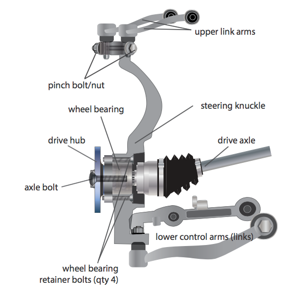
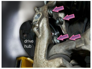
Component Locations
Here are the main components involved in this repair sequence. The illustration highlights the location of the wheel bearing, steering knuckle, and control arms.
The Audi B6 A4/S4 has a bolt-in-place bearing assembly. Four bolts secure the bearing and its holder in the knuckle. These must be loosened and removed from the rear of the knuckle after the drive axle is pulled aside.
The image is not meant to be photorealistic, and several vehicle components are not shown, including the front shock, brake caliper and rotor, and ABS wheel sensor.
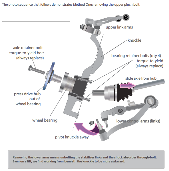
Method One: Tip Out from the Top
This repair can be done more than one way. Our preference is to disconnect both upper suspension links from the steering knuckle. This allows the top of the knuckle to be pivoted outward far enough to pull the drive axle aside, making room to remove the four bearing housing retainer bolts.
The pinch bolt that secures the upper links to the knuckle can be a problem. It has been known to seize in the aluminum knuckle and can be very difficult to remove when it does. Ours had been exposed to years of winter road salt, and it took quite a bit of twisting, pounding, and penetrant oil to free and remove it.

Method Two: Pull Out from the Bottom
Many forum posts have rightly noted the di culty of removing a badly seized upper pinch bolt. As a workaround, you can alternately disconnect the lower suspension arms and pivot the bottom of the knuckle outward. We find this approach much more time consuming and awkward. Additionally, there are several single-use fasteners that should be replaced when the lower arms are unbolted, adding to repair expense.
Installation
Step 1:
Pry out the alloy wheel center cap.
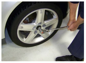
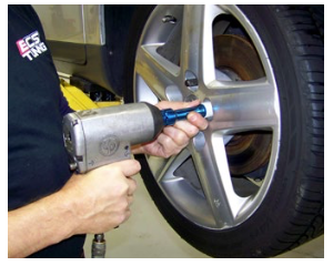
Use a large breaker bar and long 17mm hex head driver to loosen the axle nut. Do this while the car is sitting on its own weight with the hand brake engaged and/or the wheels chocked.
Note: The axle retaining bolt can also be removed with an impact gun and hex driver after the vehicle is raised and the wheels have been removed.
Step 2:
Loosen the lugs nuts and remove the wheel.
(We’re using a Schwaben® Protecta socket with plastic- coated shank to avoid scarring the alloy wheels.)
Protecta sockets are available in standard (ES6225) or extended length kits (ES2221243).
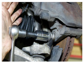
Step 3:
Reach around behind the brake rotor shield and unbolt the ABS wheel speed sensor.
Pull the sensor from the housing. A slight twisting motion will help remove it, but be sure to treat the sensor and its wiring carefully.

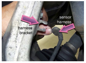
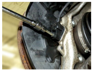
Step 4:
Carefully remove the ABS wheel speed sensor from the U-shaped bracket on the inside of the steering knuckle.
(Use caution not to stretch, kink, or otherwise damage the wheel speed sensor wire harness.)
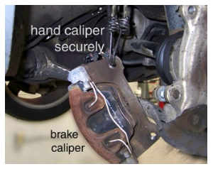
Step 5:
Using a 21mm socket, remove the two bolts holding the brake caliper frame to the knuckle.
Timesaver Tip: There is no need to remove the front brakes in pieces unless you are performing a brake service or inspection. Unbolt the carrier from the knuckle, then remove the complete caliper assembly.

Step 6:
After sliding the caliper assembly o the brake rotor, immediately support it by hanging it from a sturdy wire or heavy bungee cord.
Never let the caliper weight hang from the brake hose.
(Do not let the brake rotor fall o the drive hub as you remove the brake caliper assembly.)
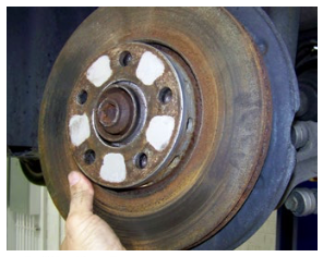
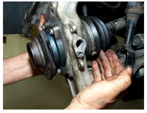
Step 7:
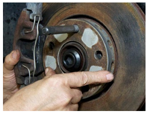
Slide the brake rotor o the drive hub.
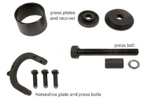
Step 8:
To help us remove the drive hub and install the hub on the new bearing, we’ll use the Schwaben Audi Rear Wheel Bearing Service Kit. (ES2561175)
While this tool set was originally designed for use on rear wheel bearings, we found it useful for replacing the front bearings, too.
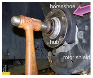
Step 9:
Install the horseshoe press piece from the bearing kit (arrow) between the drive hub and knuckle, as shown (arrow).
Unscrew the already loosened axle bolt about half an inch, and rap lightly on the bolt head to “unstick” the mating splines between drive hub and axle shaft.
When the axle is loose, unscrew and remove the axle bolt completely.
Note: We will unbolt and remove the brake rotor shield to make more room to work.
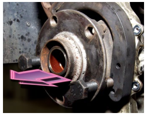
Step 10:
Thread two of the press bolts from the service kit into the drive hub lug bolt holes.
Screw them in until they contact the face of the horseshoe. Then alternately tighten the bolts to press the drive hub from the wheel bearing.
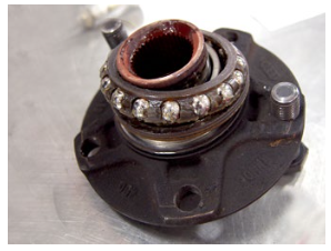
Step 11:
Both bearings usually stay inside the bearing housing as the hub comes out. This time, the outer wheel bearing comes out, and its inner race sticks to the neck of the drive hub.
The bearing cage lifts o easily enough, but the race will have to be pressed or cut o before we can reinstall the drive hub in the new bearing.
Step 12:
We’ll use a spilt jaw bearing separator (sometimes called a carrier or adjustable press plate) and a common puller to remove the bearing race.
Note: If you do not have a puller, you can use a high-speed abrasive cutting disk to cut a slit in the race. Cut almost through the race, then split it with a chisel to loosen and remove it.
Make sure you are wearing approved shop safety goggles when doing this!
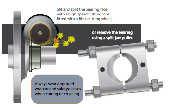
Step 13:
Here’s our setup. The split jaws grip at the base of the bearing race. The puller bolts to the jaws.
Place a flat disk on top of the hub, then turn the puller jack screw to pull the race from the hub.
Step 14:
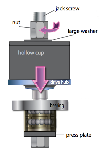
The illustration to the left shows a typical puller setup in more detail.
The wedge-shaped jaws in the split puller grip the lower edge of the inner race. Then, as the large central screw is turned, the jaws rise, pulling the race o the drive flange.

Step 15:
Use fine emery cloth to polish away small nicks or accumulations of rust. Polishing the flange neck and applying a lm of grease makes it easier to press the hub into the new bearing.

Step 16:
Now we’ll use the rest of the bearing tool to pre-as- semble the hub in the bearing housing. We work with the tool and components mounted securely in a vise for safety and convenience.
Step 17:
Here’s a closer look at the setup used to press the hub into the bearing. The large hollow cup is placed over the drive hub. The long screw jack passes through the entire assembly.
As the screw jack turns, it pushes the hub shank into the bearing inner races.
When the hub is pressed all the way in, remove the tool and lay the assembly aside while you remove the rest of the old bearing from the knuckle.
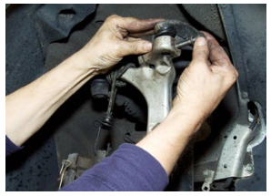
Step 18:
Remove the nut and drive out the long pinch bolt that secures the two upper link ball joints to the aluminum bearing holder (horizontal arrow).
Then use a punch to drive the ball joint studs upward from their holes in the bearing holder (vertical arrows).
NOTE: Do NOT drive a chisel or other wedge into the grooves at the ball joint studs (red arrow). You’ll crack the aluminum housing and damage it, making the car unsafe to drive.

Step 19:
This photo shows the long pinch bolt and upper links removed from the bearing holder.
With the upper links disconnected, we can pivot the bearing holder outward.

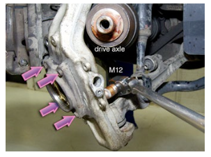
Step 20:
Tilt the bearing holder outward far enough to pull the drive axle o to the side to make working room.
Using an M12 driver, loosen the four bearing retainer bolts; back each out about 1/2-inch.
Step 21:
Rap on the heads of the loosened bolts to break
the bearing housing free from the bearing holder. A hammer works; an air chisel with a flat head hammer bit does wonders pounding out corroded-in-place housings.
When the housing breaks free, remove the four bolts completely. Slide the bearing housing out of the knuckle. Discard the holder and bolts.

Step 22:
It may be necessary to clean out the bearing holder. Ours is coated with heavy accumulations of road salt from many Ohio winters.
A drill-mounted wire wheel removes the heavy crust. Take extra time to clean the mounting face where the bearing housing sits.

Step 23:
Slide the new bearing assembly with hub into the steering knuckle. Align the threaded holes in the housing with the through-holes in the knuckle.
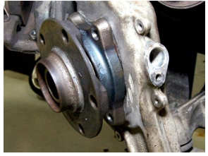
Step 24:
Slide the four new bearing retainer bolts through the holes in the steering knuckle. Screw them into the threaded holes in the wheel bearing housing.
Alternately tighten the four bolts until the bearing housing is drawn tight against the knuckle face.
These are torque-to-yield bolts; new ones must be installed with the new bearing housing.
Step 25:
Torque the bolts to 80Nm (60-ft-lb), plus and additional 90 degrees.

Step 26:
Align the axle with the center of the bearing and slide it into the drive hub. Rotate the drive hub back and forth by hand until the splines in the hub align with those on the outer drive joint.
Step 27:
Screw the new axle bolt into the outer drive joint to keep the axle and hub engaged. Using a 17mm driver, hand tighten the bolt, for now.

Step 28:
Tip the top of the knuckle arm inward again and reattach the two top pivot arms. Insert the ball joint studs from both arms into the knuckle. Then slide the pinch bolt into the hole in the knuckle to lock the ball joints in place.
Install a new lock nut and torque the pinch bolt to 40Nm (29.5 ft-lb).
Step 29:
Reinstall the rotor shield, if you have removed it.
(This is a great time to clean the old shield and apply a fresh coat of paint, especially if you live where roads are heavily salted in winter.)

Step 30:
Reinstall the brake rotor and caliper assembly. The ECS Tuning Wheel Hanger Installation Guide Tool (ES5965) is handy here for holding the rotor steady as you slide the caliper in place and bolt it to the knuckle.
Step 31:
Tighten the caliper bolts evenly by hand. Then final torque them to 75 Nm (55 ft-lb).
A few drops of thread locking compound adds peace of mind. Loctite 242 (medium strength blue) will suffice.
Step 32:
Reinstall the ABS wheel speed sensor. Take a moment to wipe away any debris or metal shavings that may have accumulated on the head of the sensor, since they can a ect sensor operation.
Step 33:
Reinstall the wheel and tire. Torque the wheel bolts to 120Nm (89 ft-lb).
Lower the car until it sits on its own weight. Lock the brake or chock the wheels so the car cannot move. Then torque the 16mm torque-to-yield axle bolt to 200Nm (140 ft-lb, plus an additional 180 degrees).
Replace the center cap.
This completes the Audi B6 A4 front wheel bearing installation.
Interested in purchasing?
Go to ECSTuning.com >Log into your vehicle>Drivetrain>Wheel Bearings